Triangle Drawing – Verilog

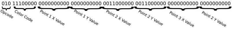
With the Bresenham Line Drawing implemented in Verilog last semester, the main goal for this semester was to take that implementation and generate triangle coordinates in a new Verilog program. This was done by creating two different scenarios, a flat bottom approach, and a flat top approach. Given three coordinates, with one side being a flat straight line, the Verilog program will then provide the coordinates needed for a triangle drawing.

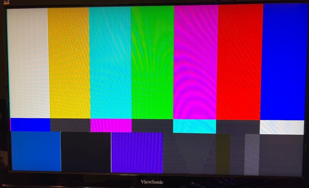
The figure shown below demonstrates the functioning triangle drawing program in our first successful demo run.

Image

Command Processor

With the display engine, frame buffer, and line drawing algorithm implemented, next a command processor was designed to parse instructions and send data to their proper places. This processor takes a 71-bit input data stream and outputs the data to other modules depending on the opcode provided.

Bresenham’s Line Drawing Algorithm

The next objective of this project was to implement a module that functioned as a Bresenham’s Line Drawing State Machine. Given any two input coordinates, the module would output discrete coordinates for each point along the line to be inserted into the frame buffer, with high efficiency. Due to our single clock domain system, we reached a near-perfect efficiency of 1 pixel write per clock cycle, wasting only a single cycle at the beginning of each line drawn.

Frame Buffer

Implementing a frame buffer allows the display engine to output pixels as defined in memory. Using dual-port RAM, we can read and write at the same time.

Using a function to convert an x,y pixel address to a memory address, the display engine can directly retrieve pixel data with the frame buffer. The function for this is as follows:

MemoryAddress = Hcount + 800 * Vcount

Where Hcount and Vcount both start at 0 and increment until they reset. Loading the frame buffer with default data allows us to display a test pattern.

Display Engine

The first deliverable for this project was creating a display engine that could properly drive a VGA display at 800×600 resolution. In order to do this, a Vsync and Hsync signal must be generated that matches VGA specifications.

Using a pixel clock of 40Mhz an Hsync signal must be low for 840 pixel clock periods, high for the next 128 periods, low for the following 88 periods, and repeating. Using a module to count these periods, we were able to recreate this Hsync signal to match this criteria.

To create the Vertical Sync signal, we used the horizontal counter to increment a vertical counter on every horizontal counter reset to indicate a new line. Using this counter the Vsync signal will be low for the first 601 vertical lines, high for 4 lines, low for 23 lines, and repeat.

Outputting these signals to a VGA display yields the following results: