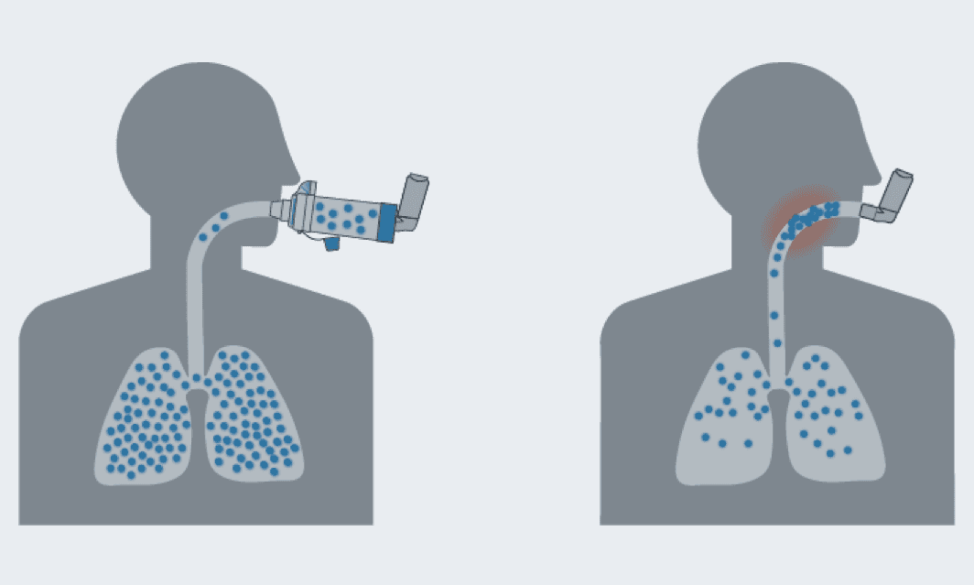


The Smart Spacer System is used to improve the delivery of aerosol drug delivery. Though parts of the design remain in progress, the anticipated technologies, structural assemblies and electrical implementation are explored in this chapter. These aspects of the design have been selected to meet the project’s functional safety and useability objectives.
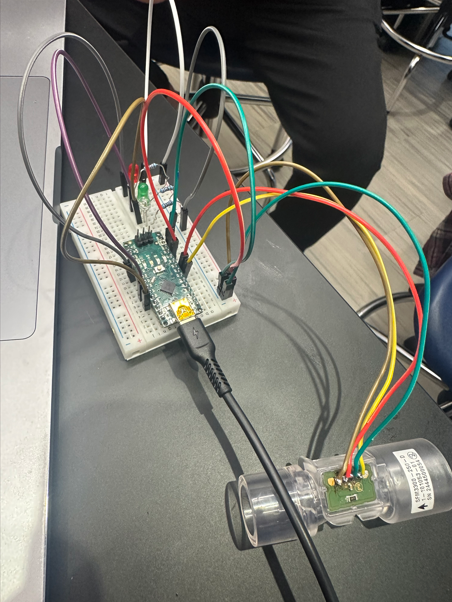
An arduino micro microcontroller will handle data processing and combine feedback from sensors to trigger the LED indicators. The arduino micro is perfect for this application as it is very compact in size and has enough I/O pins for the device’s function. The Sensirion SDP 3x Series pressure sensor will be used to measure pressure changes which will provide the measurement necessary to prompt instant visual feedback. A series of energy efficient LEDS will help guide users during their inhalation. A simple red, yellow and green indicator will be used to guide the user into inhaling properly. The red light will tell the user when to stop inhaling. The yellow light will indicate when the device is idle. Lastly, the green light will indicate users when to inhale. The device will be powered with a rechargeable LiFePO4 battery. This component was specifically chosen for its long lifespan and overall useability.
The Smart Spacer System itself comprises three major assemblies. The attachment site will utilize an adaptable clamp to connect the spacer to a range of different inhaler types. This will ensure the device is compatible with a variety of inhaler brands and sizes. The second part is the holding chamber which is responsible for slowing down the aerosolized medication. This component will be the largest of the device. The last component will be a compartment where all electrical components are housed. This design will include a compact compartment to protect sensitive components and allow for assembly/disassembly and battery replacement. The three components can be separated from one another through a series of connectors. This feature of the design allows the device to be easily transported and cleaned complying with ISO 23747.
The microcontroller will be securely placed inside the electronics compartment. The goal is to either wire through a PCB or directly through the LEDS and pressure sensor. The pressure sensor will measure the change in pressure in the device and send information to the microcontroller so the LED can be turned on. Implemented LEDS on the surface of the device will act as a guide for users to ensure proper inhalation technique. The use of ABS plastic provides a strong but lightweight frame. This material is perfect for the intended use of the device due to its adherence to health and safety standards.
As the final design evolves more detailed CAD models and prototypes will be developed. The final component integration will be validated by testing the reliability of the feedback system and ensuring the device is accurate. Further tweaks will aim to improve the layout and overall design of the device.
————————————————————————————————————–
Pin Assignment

Differential Pressure Sensor
- A4 SDA (Dataline)
- A5 SCL (Clockline)
- Bi-directional logic converter
LEDS
- D2
- D3 (PWM)
- D4
- Anode through CLR
Power Button
- D5 (PWN)
Pins Available
- D6 (PWN), D7, D9 (TXD), D10, D11, D12, D13
- A1, A2, A3, A6, A7