
October
We are starting to define our device requirements. Upon careful research of DVT and poor venous return the team has decided that the device should meet the following requirements:
- Device must sense calf and ankle swelling.
- Device must begin cyclic mechanical compression when swelling is detected.
- Device must be able to function in limited space environments.
- Device must operate over the length of a workday.
- Device must fit the calf circumference, ankle circumference, and tibial length of adult/male female.
- Device must incorporate a manual shut off.
- Device must monitor pressure.
- Device must operate at low noise emission.
- Device must meet IEC 60601 standard.
The previous requirements are justified below:
- An indication of poor venous return is calf swelling, which can lead to deep vein thrombosis. [1,2] The ankle will serve as a second point of measurement for indication of poor venous return. [3]
- Mechanical intermittent compression has been shown to improve venous return when placed around the lower leg and foot. [4-7]
- Populations that have low mobility (truck drivers, office workers, etc.,) are at increased risk for DVT. They have limited space available in their working environments, therefore require a small device. [8]
- Device will be used by populations that are immobile for long periods of time during their workday. [8]
- Risk of DVT is observed in both adult men and women with a slightly higher occurrence in men. [9]
- Patients may experience varying levels of discomfort, thus a user operated shut off switch is necessary.
- Will serve as a safety mechanism in order to keep the device from outputting a pressure greater than is safe for the patient.
- In public work settings, noise can distract fellow workers. Thus, the device must operate at a low enough noise level to minimize distractions.
- Since the device is powered and in direct contact with the patient’s leg, it must meet electrical safety standards for biomedical devices.
Citations:
- Douketis, J D. “Deep Venous Thrombosis (DVT)”. Merck Manual Professional Version. (2021)
- Gorman, W Peter et al. “Swollen lower limb: general assessment and deep vein thrombosis.” Western Journal of Medicine vol. 174,2 (2001): 132–136.
- Brodovicz, Kimberly G et al. “Reliability and feasibility of methods to quantitatively assess peripheral edema.” Clinical medicine & research 7(1,2): 21-31. (2009)
- Zuj, K A et al. “Enhanced muscle blood flow with intermittent pneumatic compression of the lower leg during plantar flexion exercise and recovery.” Journal of applied physiology (Bethesda, Md.: 1985). 124(2): 302-311. (2018)
- Delis, K. T et al. “Optimum Intermittent Pneumatic Compression Stimulus for Lower-limb Venous Emptying.” Eur J Vasc Endovasc Surg 19, 261–269. (2000)
- Vowden, K. “The use of intermittent pneumatic compression in venous ulceration.” British journal of nursing (Mark Allen Publishing). 10(8): 491-509. (2001)
- Hartman JT, Pugh JL, Smith RD, Robertson W
- Suadicani, Poul et al. “Jobs encompassing prolonged sitting in cramped positions and risk of venous thromboembolism: cohort study.” JRSM short reports. 3(2):8. (2012)
- Andreou, E Roseann et al. “Differences in clinical presentation of deep vein thrombosis in men and women.” Journal of thrombosis and haemostasis : JTH. 6(10): 1713-9. (2008)
November
Over the past month the team has finalized device specifications:
| Device Specifications |
|---|
| 1.1-Detect difference in calf circumference of >2% in comparison to initial input. [1] 1.2-Detect difference in ankle circumference of >11% in comparison to initial input. [2] |
| 2.1-Cycle time of 15 +/- 2 seconds and pressure from 60-80 mmHg(resting), 120-140 mmHg (peak pressure). [1] 2.2-Time to reach maximum compression of 0.5-2 seconds and decompression of 11 +/- 2 seconds. [1] 2.3– Compression begins when there is >2% difference and >11% difference in calf and ankle circumferences respectively. Compression ends when a <2% difference and a <11% difference in calf and ankle circumferences respectively. [1] |
| 3.1-For upright and reclined seating postures in an office environment the dimensions of clearance are 50 cm wide, 45 cm deep at knee level, and 60 cm deep at foot level [3] 3.2-Standard leg room ergonomic dimension for truck driver is 90cm wide, 60 cm high, and 75 cm in depth. |
| 4.1-Device will be battery operated (rechargeable) over a 11-hour workday. [4] |
| 5.1– Device will fit a calf circumference of 28.2 to 40.7 cm. [5] 5.2-Device will fit tibial length of 30.8 to 46.5 cm. [6] 5.3-Device will fit an ankle circumference of 20.6 to 25 cm. [5] |
| 6.1-The button will be located at the highest point on the device, closest to the knee for easy access. The button will be no > 1 inch below the knee. 6.2-Stop all compression and release all pressure in a time no more than 2 seconds.[1] |
| 7.1-Must monitor pressure between 0-150 mmHg +/- 5 mmHg. [1] |
| 8.1-Must operate at noise levels less than 45 dB [7]. |
| 9.1-Device shall not exceed leakage current of 10 mA RMS. [9] |
We have also considered various design which are shown below:
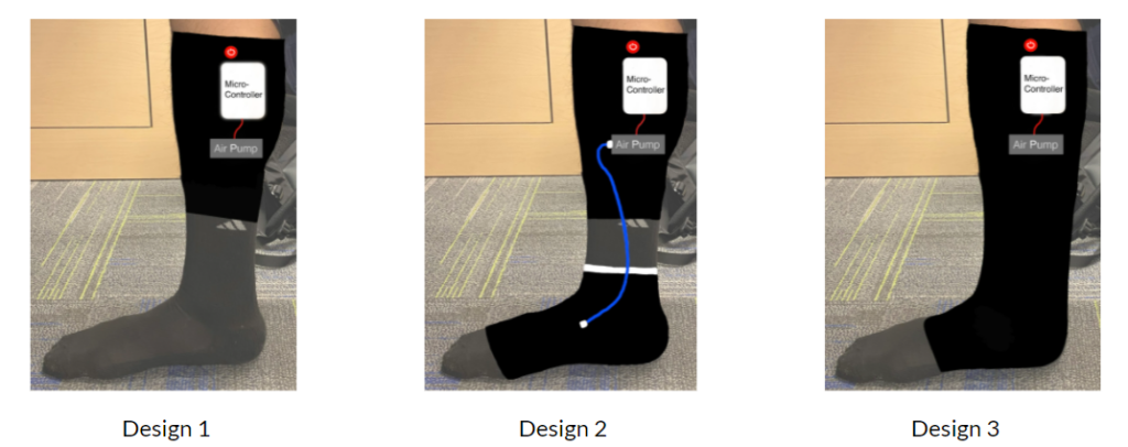
The first design incorporates a cuff around the calf muscle. Design 2 features a detachable cuff design, which will allow the user to remove the ankle cuff. The second design was considered since research supports that calf and foot pneumatic compression increases venous return more than calf alone [1]. The third design features compression all through-out the lower leg.
Citations:
- Delis, K T et al. “Optimum intermittent pneumatic compression stimulus for lower-limb venous emptying.” European journal of vascular and endovascular surgery : the official journal of the European Society for Vascular Surgery vol. 19,3 (2000): 261-9. doi:10.1053/ejvs.1999.1047
- Brodovicz, Kimberly G et al. “Reliability and feasibility of methods to quantitatively assess peripheral edema.” Clinical medicine & research 7(1,2): 21-31.(2009)
- “Upright and Reclined Seated Postures”. United States Department of Labor. Occupational Safety and Health Administration.
- Hege, Adam et al. “Occupational health disparities among U.S. long-haul truck drivers: the influence of work organization and sleep on cardiovascular and metabolic disease risk.” PloS one. 13(11). e0207322.(2018)
- Karakaş, P., Bozkir, M.G. Determination of Normal Calf and Ankle Values Among Medical Students. Aesth Plast Surg 31, 179–182. (2007).
- Aitken SA. Normative Values for Femoral Length, Tibial Length, and the Femorotibial Ratio in Adults Using Standing Full-Length Radiography. Osteology.1(2):86-91. (2021)
- Connor, Alison, and Elizabeth Ortiz. “Staff solutions for noise reduction in the workplace.” The Permanente. 13(4): 23-7. (2009)
- IEC 60601-1: 2012, Product Safety Standards for Medical Devices- Part 1: General requirements for basic safety and essential performance
December
In order to measure circumference differences in the calf we have considered various sensors. We have looked at both capacitive and resistive sensors and have decided upon a resistive stretch band to detect displacement changes. Additionally, the past few weeks have been spent creating protocols for validation and verification testing, which will be performed in the spring.
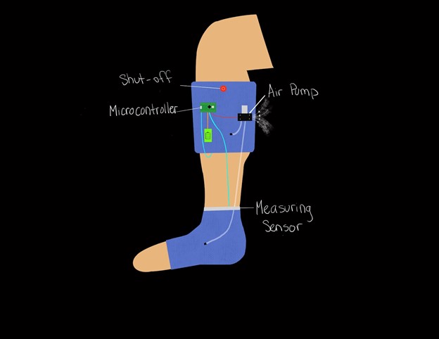
The team has also decided upon a final design using a decision matrix. We have chosen second design solution with a detachable foot cuff.
Displacement sensors will be placed on the calf and ankle of both legs. The ankle sensor serves to confirm calf swelling. Pressure sensors will be attached within each compartment, to assure that specified pressures are being reached and maintained.
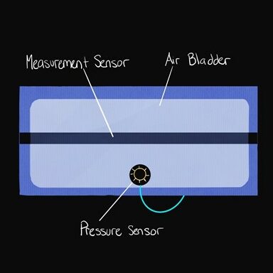
Alternative compression methods were considered such as a DC motor driven compression band, but it was ultimately decided that pneumatic would allow for the most comfort within the patient. A sketch of the final design and cuff layout is shown below:
December-January
The team is working to finalize all component selection during winter break. Wiring diagrams are also being drawn out for each sensor the microprocessor. We will be building and assembling throughout winter break.
February
Team is finishing up receiving components. We are testing all components individually before full assembly.
This past month the force sensing resistors (FSR) have been calibrated. We have calibrated these sensors using brass weights on the contact surface. The following relationship has been attained:

This calibration will allow us to monitor when the device is reaching the desired pressure points of 60-80 and 120-140. Compression will be modulated based on the pressure sensed by these sensors.
Additionally, the team has decided to use a conductive stretch sensor to measure displacement changes. When this sensor is stretched, resistance changes, which can be correlated to a displacement value. Further testing will be performed in March to achieve an accurate calibration that can be implemented in the control code.
March
This past month the team has been working on testing the relay and air pumps. A mock code has been written that allows the pumps to inflate the bladders to a maximum pressure and then turn on a second deflation pump. Second deflation pump was used in order to control 11 second deflation time.
Calibration of the conductive stretch sensor was performed. A voltage-displacement relationship was determined by stretching the sensor over 0.25 cm increments. Displacement sensor code was written up, which when displacement is greater than 2% and 11%, in the calf and ankle respectively, activates the compression cycle.
By the end of the month, it was decided that there too many wires hanging loosely from the device and that a protoboard should be used to solder all connections coming from the eight sensors.
April-May
Over the past month the team has been finalizing the prototype. All wiring has been soldered to a protoboard and properly insulated. The code has been finished up and is properly working. The conductive stretch sensors monitor displacement changes and activate the compression cycle. The stretch sensor is shown below:

The inflation pumps fill to a maximum compression pressure of 130 mmHg which is checked by the FSR sensors. For deflation a relay opens and lets a deflation pump suck out air from the bladders.
Additionally, the last component of the device was ordered. An 88 Watt-hour battery was chosen based on the power draw of the individual components. The battery chosen is shown below:

The full wiring schematic for our device is shown below:

We have started to perform our verification and validation testing. We have had the privilege to gain access to the nursing simulation lab. We will be performing some verification and validation testing:

For the rest of the month, we will continue to finalize our design and finish verification and validation testing.