Responsibilities, Considerations, & Requirements
The frame is essential in the design process as it must incorporate all subsystems including: steering, braking, drivetrain, and ergonomics. Thus, the design of the frame must be developed while considering these subsystems. Another major component of the frame is material selection. Materials such as aluminum, steel, and carbon fiber can be considered while also keeping in mind the overall budget and manufacturing capabilities of the project. After determining the material and geometry, proper analysis must be conducted in order to confirm the HPVC design and safety requirements are met. After the design is finalized, the frame manager is expected to take charge during manufacturing to ensure everything is complete and integrated in a timely manner, and eventually lead testing on the vehicle. Frame safety requirements as prescribed by ASME are as follows:
- Rollover Protection System (RPS) which prevents all riders from coming into contact with the ground in the event of a partial or full rollover.
- A 2670 N rear-facing applied load 12° from the vertical, with a maximum deflection of 5.1 cm.
- A 1330 N side load applied at the shoulder joint, with a maximum deflection of 3.8 cm.
Material Selection & Decision Matrix
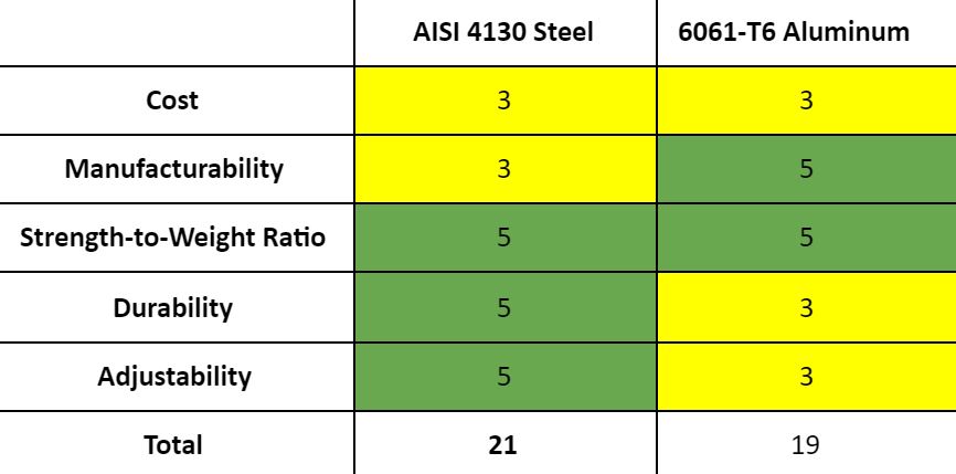
Due to feasibility and effectiveness, the possible frame material was narrowed down to either Aluminum Alloy 6061-T6 or Steel Alloy AISI 4130. The decision matrix created by the team can be viewed below, with some of the most essential factors in the team’s decision as follows:
- Budget
- Simplicity of Design
- Adjustability
- Strength and Stability
Interim Design (10/28/20)
- Material: AISI 4130 Steel
- Stock Sizes
- 1″ round tubing (0.065″ thickness)
- 1.25″ square tubing (0.065″ thickness)
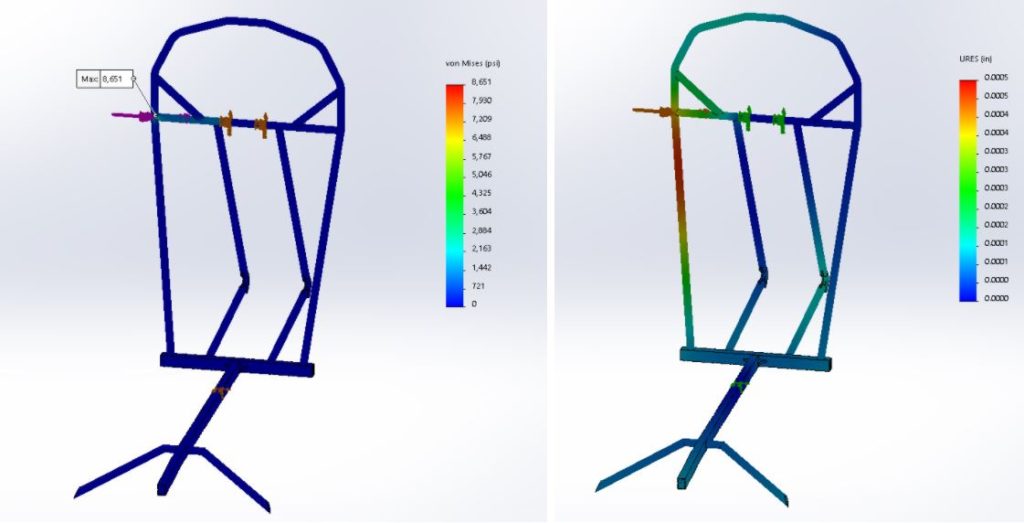
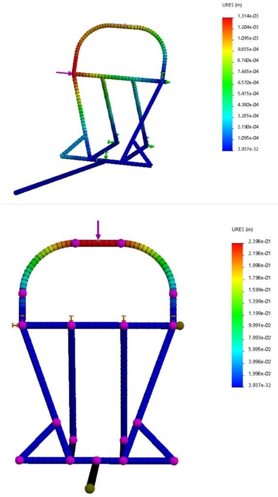
Solidworks modeling was used to find the load response in the form of stress distribution and displacement for the side (above) and top (below) loadings.
Top Load 2670 N (600 lb)
- Max. Deflection of 0.240″ < 2″ allowed
Side Load 1330 N (300 lbs)
- Max. Deflection of 0.0013″ < 1.5″ allowed
Final Design (1/26/21)
Material: AISI 4130 Steel
Stock Sizes:
- 1.5″ x 1″ x 0.065″ rectangular tubing (green)
- 1″ O.D. round tubing, 0.065″ (yellow) and 0.048″ (red) wall thicknesses

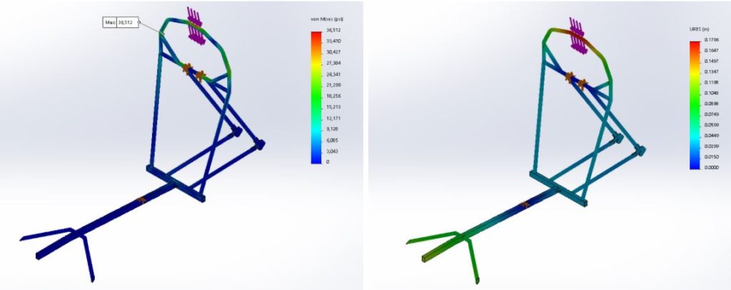
Top Loading (2670 N)
- Max stress of 36,500 psi (F.O.S. = 1.8)
- Deflection of 0.180″ < 2″ allowed
Side Loading (1130N)
- Max stress of 8,700 psi (F.O.S. = 7.7)
- Deflection of 0.001″ < 1.5″ allowed