

Responsibilities, Considerations, & Requirements
This role corresponds to designing and manufacturing the power-generating system of the vehicle: consisting of the front sprocket-and-pedal connections, as well as the rear gear hub. The system will be designed in order to provide the rider with multiple gear ratio combinations that can provide different amounts of rotational speed and power generation to accommodate the different trials. It is the drivetrain manager’s responsibility to design and construct a fluent and working system that smoothly integrates with the rest of vehicle components. It is also the responsibility of this student, along with the ergonomics and frame design managers, to assess and determine how to account for varying rider heights, whether that be with a movable boom or an adjustable seat. Testing of last year’s bike (which incorporates a movable boom) as well as supplementing research will be used to make this decision.
Interim Updates (10/28/20)
In order to limit expenses, the team decided to re-use a large number of parts from the shop’s inventory to construct our rear-wheel drivetrain system, including the following:
- Rear gear cassette
- 53-tooth front pedal-sprocket
- Chain
- Derailleur and gear shifter
The team has decided to design the exact chain path after the finalization of the frame and steering geometries to allow for the best possible integration amongst all subsystems. Last year’s movable boom system proved to be an issue during manufacturing, with the chain continually slipping off of the weak tensioners put in place to adjust the chain length for different riders. So, this year’s team has placed an emphasis on eliminating the movable boom and adjusting for variations in rider heights using a movable seat.
Gearing
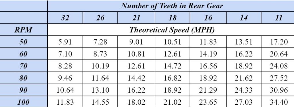
The team decided upon a maximum sprint speed goal of 30 mph given its feasibility and applicability to other successful HPVC teams. After checking our inventory, the gear ratio and rear wheel diameter were used, along with a reasonable assumption of 100 rpm in a sprint race, to find the maximum velocities at each gear combination, seen in the table below. Taking into consideration the average strength of all riders, this should make a 30 mph velocity achievable for the short sprint races.
Final Design (1/26/20)
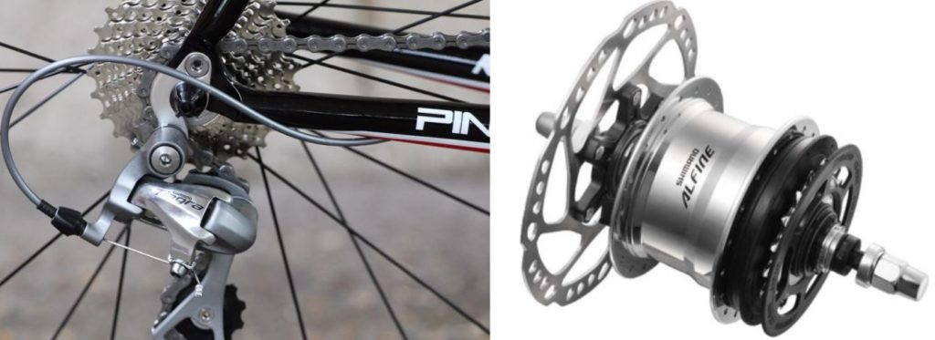
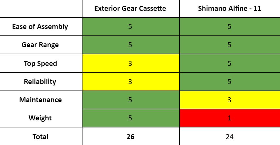
The team opted to utilize the exterior gear cassettes (left) as opposed to the Shimano Alfine 11 internal gear hub system (right).
Key Design Points
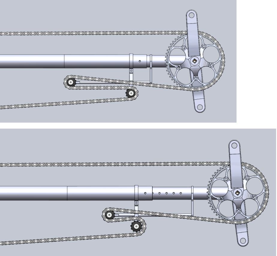
- Tension is kept through entire drive-side to ensure effective power conversion
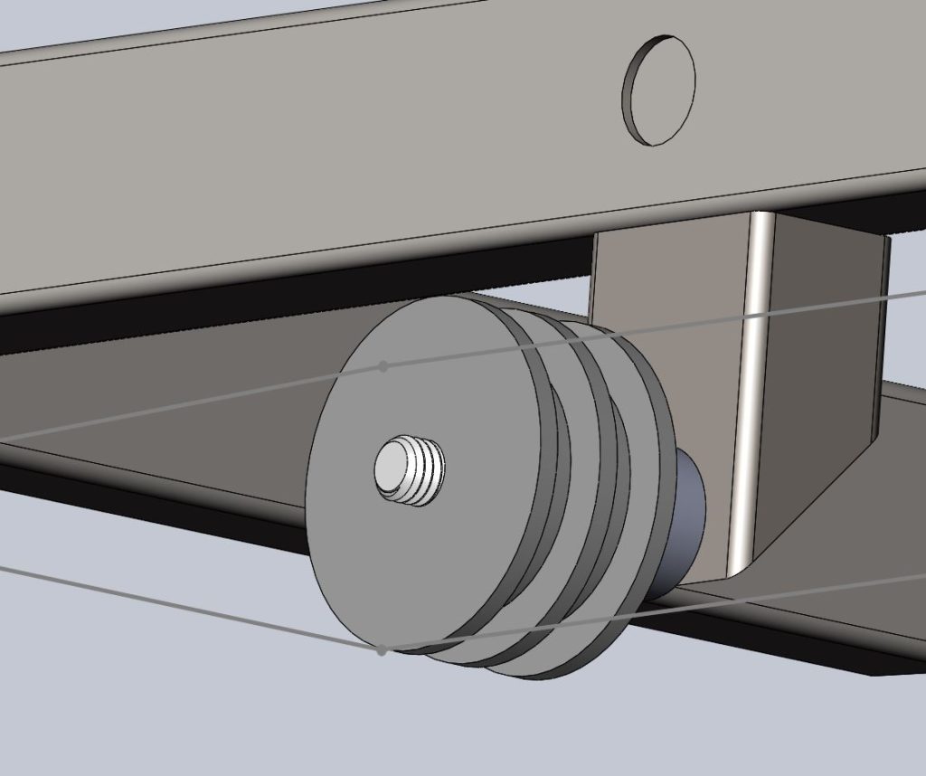
- Two different idlers are used to redirect the chain
- Chain tubes for drive and return sides mounted to the moving seat carriage to protect the legs of the rider
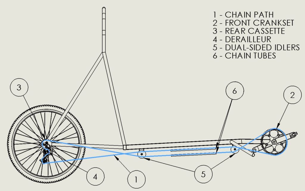
path shown in gray)