Responsibilities, Considerations, & Requirements
The design of the vehicle’s steering and braking systems must be as light as possible to conserve weight, whilst still allowing for proper performance. The steering will be designed to the specifications of two-wheel Ackerman steering in order to optimize the turning radius of the bike, and allow it to fit the ASME HPVC rules and guidelines. Anthropometrics and ergonomics will be taken into heavy consideration when designing the steering mechanism, as it is necessary for the rider to comfortably ride the bike for long periods of time. Adjustability will also be a factor in the final design choice. The steering will be driven by one of the following three options:
- Conventional steering column and wheel
- Knuckle-mounted handlebars
- Under-seat mounted handlebars
The existing bike from this past year (which uses knuckle handlebars) will be tested to determine which of the three systems will be implemented. Front wheel braking will be accomplished by using stock disk brakes, mounted on the steering wheel or the handlebars, depending on which option will be chosen for the final design. Back wheel braking will be accomplished with a stock over-wheel mounted caliper brake. The brakes will be selected and thorough analysis will be performed so that the stopping distance requirement, outlined by the ASME, will be met. Both the steering and braking systems must not interfere with each other, the other systems of the vehicle, nor the comfort of the rider so the vehicle operates efficiently and safely.
Interim Design (10/28/20)
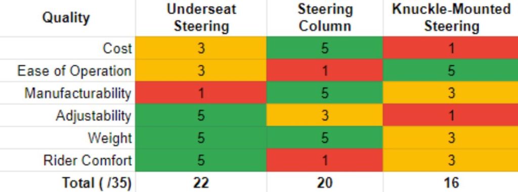
The three steering mechanisms listed above were considered to implement in this year’s vehicle. Among others, cost, adjustability, and manufacturability were some of the major factors taken into account (see Decision Matrix below).
Steering Decision Matrix
Current Design
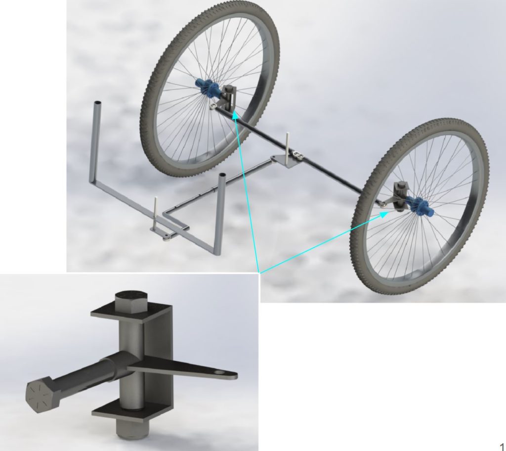
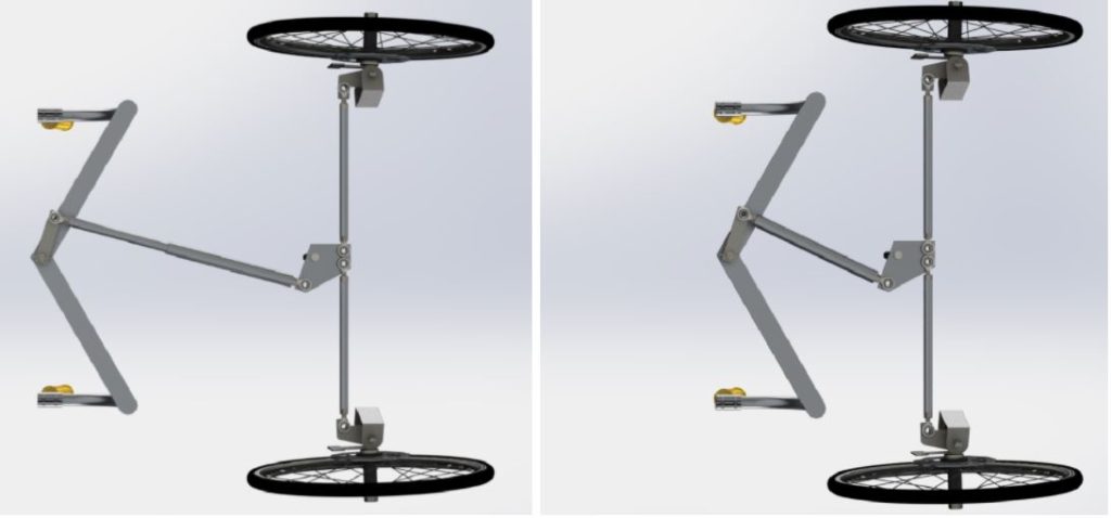
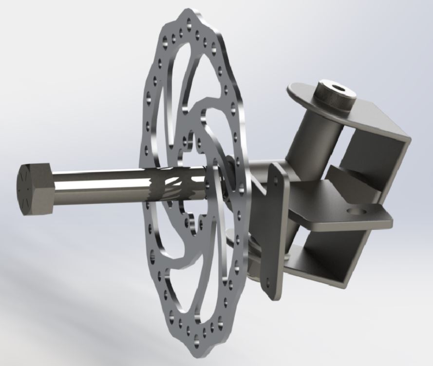
The team’s current design uses a longitudinal tie rod to connect the pitman arm to a bell crank at the front end, which transmits the front-to-back motion of the longitudinal tie rod to the lateral motion of the front tie rods. The white pivots in the figure are where the system will be anchored to the main beam of the bike. The rear pivot point in particular will be anchored to the adjustable seat carrier so the steering can be adjusted in tandem with the seat. The longitudinal tie rod is bent to allow the bell crank to be anchored to the frame, while at the same time allowing intuitive bicycle-style steering. You can see our knuckle design in the bottom figure, where the Knuckle bracket is made of 4130 steel channel stock, with a tool steel pivot, and hardened steel bolts acting as the kingpin and spindle.
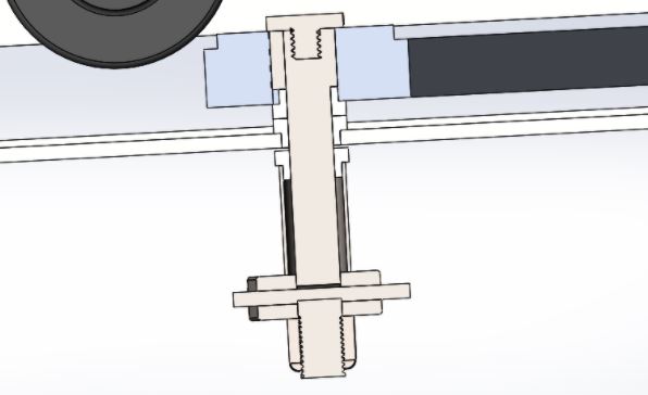
Adjustable Steering
As opposed to manufacturing adjustable handlebars, the team decided to create an adjustable tie rod. The design uses two telescoping pieces of Aluminum 6061-T6 tubing, secured with a 1/2″ steel button pin. Three adjustment points will be included to accommodate the three relative height ranges of the team members. The videos below show brief examples of the steering geometry in motion.
Final Design (1/26/21)
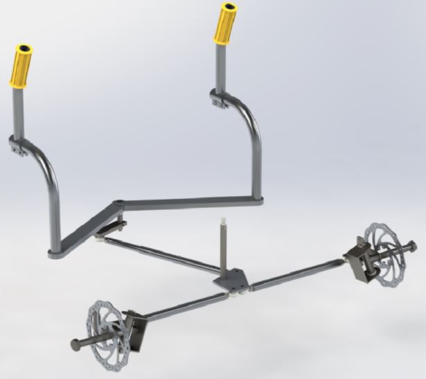
Major Design Components
- Under-seat handlebars coupled to pitman arm beneath seat carriage
- Pitman arm pushes adjustable longitudinal tie rods, which rotate the bell crank
- Button-pin used to adjust the tie rods simultaneously with the adjustable seating
- Bell crank translates longitudinal motion to lateral motion through the push/pull of front lateral tie rods that are connected to the wheels through steering knuckles
Steering Geometry
- 6º positive caster angle (assists in self-centering)
- 3º negative camber angle (prevents skidding and evens tire wear)
- 2º toe-in angle (limits excessive sensibility of steering system)
- Kingpin inclination (absorbs force from rough terrain more effectively, and allows inner wheel to rotate faster than outer wheel during turns)
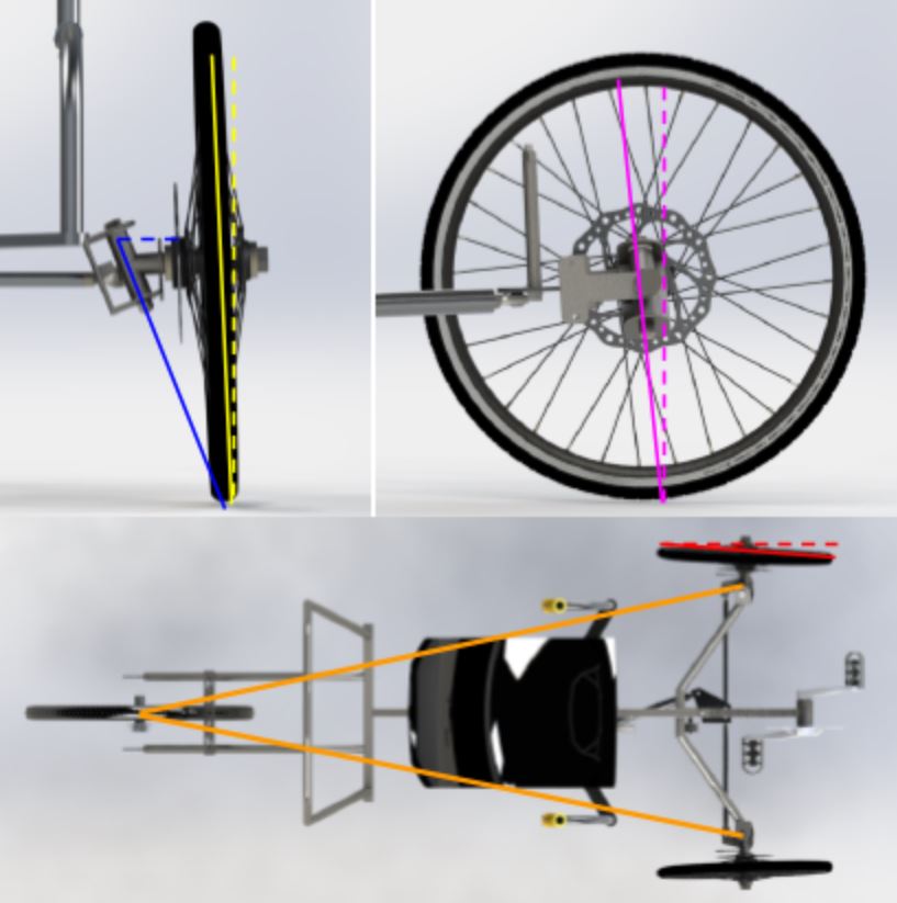
Ackerman = Orange)
Braking
- Mechanical disc-caliper front braking (welded to knuckle mounts)
- Mechanical rim-caliper rear braking