
A. Frame
Test A1: Top Loading
Date:
Purpose: -Ensure safety of rider in event of complete flip over
-2670 N (600 lbs) applied to rollhoop at 12𝆩 from vertical
-Max (expected) deflection: 0.240” < 2” allowable deflection
Procedure: -Strip frame of non-essential materials
-Use wooden boards to brace frame, as well as tilt at 12 degree
incline, and clamp
-Load appropriate amount of weight onto chain and apply load
to the roll hoop
-Use dial test indicators to find deflection
Test A2: Side Loading
Date:
Purpose: -Ensure safety of rider in event of vehicle tip over onto side
-1330 N (300 lbs) applied to rollbar at shoulder height
-Max (expected) deflection: 0.0013”< 1.5” allowable deflection
Procedure: -Strip frame of non-essential materials and place on side
-Use wooden boards to brace frame and clamp in place
-Load appropriate amount of weight onto chain and apply load
to the shoulder joint
-Use dial test indicators to find deflection
Test A3: Rollover
Date:
Purpose: -Ensure rider safety in the event of an accident. No rider body
part is to make contact with the ground in the event of a roll
over.
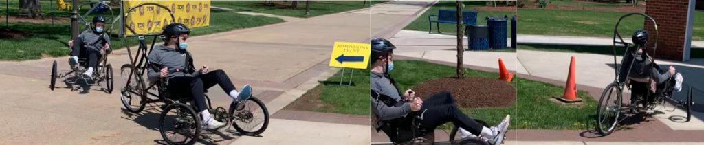
Procedure: -Largest group member (Matt), sits in vehicle and secures safety
harness over shoulders and lap
-Remaining team members flip vehicle on its side and ensure none
of Matt’s body parts are in contact with the ground.
-Flip the vehicle completely upside down and ensure none of Matt’s
body parts are in contact with the ground.

-Side: hand barely skims ground; rider is protected especially if shoes are strapped to the pedals
-Full: bike shoes weren’t fitting so the riders feet detached from pedals, not enough room for total knee clearance
B. Steering & Braking
Test B1: Turning Radius
Date:
Purpose: -To ensure turning radius fulfills ASME requirement of 8.0m
(26’3”), test against group goal of under 5.0m (16’5”)
Procedure:-Use chalk to mark three lines on the pavement: one for
exterior wheel location at the start of the turn, one 5 m from
the base mark, and another 8m from the base mark.
-Build up necessary, yet not excessive, speed to comfortably
make a 180 degree turn in the vehicle while lining the exterior
wheel up with the base mark made with chalk.
-Begin the sharp turn, with a group member recording at an
optimal angle to be able to review if necessary.
-Have another group member watch the turn diligently and
mark an estimate of the location of the exterior wheel after
completing the turn (confirm with video)
-Use tape measure to record turning radius
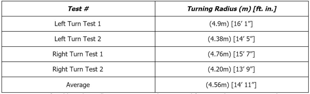
-Comfortable cadence (but not sprint pace) is required for optimal turning
-Steering subsystem seems to more easily rotate to maximum stroke when turning right, although the results are not drastically different suggesting this may be more of a comfort issue.
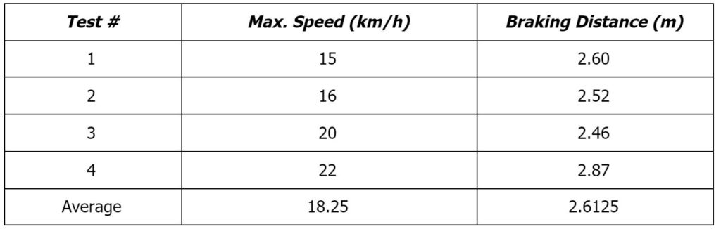
Test B2: Braking Distance at Max Speed
Date:
Purpose: -To ensure vehicle fulfills ASME requirement of stopping from a
speed of 25 km/hr over a distance of 6.0m
Procedure: -Measure out a stopping zone of 6 m at the end of a smooth,
straightaway path.
-Set up the speedometer on the bike and ensure that it is
properly calibrated.
-Rider rides vehicle down the straightaway, ensuring that a
speed of at least 25 km/hr is reached.
-Begin to brake at the start of the 6m stopping zone. Ensure
vehicle comes to complete stop in 6m zone
-Acceleration zone was straight asphalt path, approximately 50 yards long
-The team made numerous attempts to reach the 25 km/h mark set by the ASME competition, but failed to reach it. They believe this is due to the difficulty that the seat orientation causes when trying to pedal at high cadences, with a possible solution being further back support.
C. Drivetrain
Test C1: Max Speed
Date:
Purpose: -To test the success of the design. Verify that goal maximum
speed of 34 mph is reached, while steering remains functional to
keep vehicle straight
Procedure: -Rider rides along straightaway at full speed.
-Record maximum speed displayed on speedometer, and
distance necessary to obtain this speed.
-Ensure a straight path can be ridden at this speed indefinitely
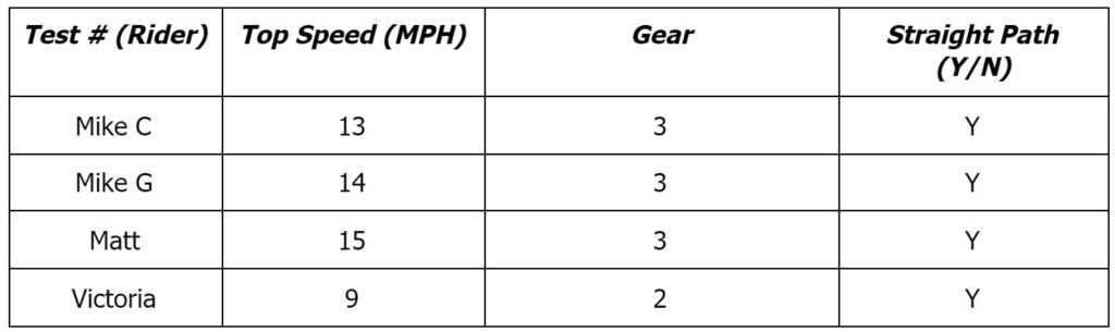
-Clearly, projected max speed of 35 mph was not attained. The gearing proved much too difficult to be able to shift to the lower two gears.
-Rider orientation was not ideal for power generation. Solutions could be better back and shoulder support.
-For lighter, weaker riders, the first and second gears were the only attainable options, making it hard to generate good speed.
-Riders had a 100 yard warm up loop, with a 50 yard straightaway to attain maximum sprint speed.
Test C2: Endurance
Date:
Purpose: -To mimic the endurance race set up by ASME.
-To ensure durability and stability of the vehicle over an extended
riding time and ensure quick adjustability while changing rider
height.
Procedure:-Set up team members along path to watch for pedestrians, and
cones for slalom course
-Team members alternate riding through the course, ensuring
the vehicle runs smoothly and is stable.
-Make sure vehicle comes to complete stop before incline by
recreation center
-Each member rides through the course for a total of 2 laps (one
lap approx. 0.75 miles)
-Record overall time.
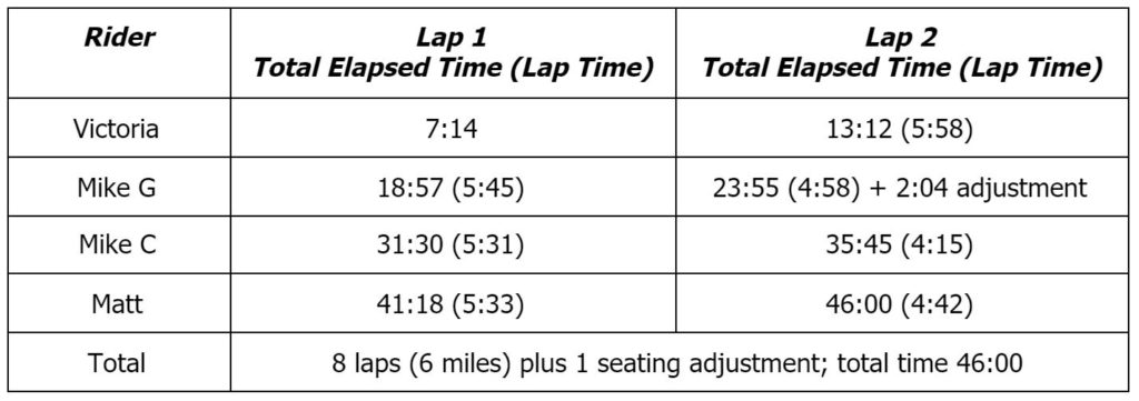
- All riders successfully climbed both inclines; by recreation center and
and dining hall
- Chain fell off the back of the cassette in fifth lap due to derailleur cable having too much tension; quickly fixed for about a fifteen second loss in time
- Screw fell off of the front right brake on lap four, causing front brakes to malfunction. Team completed the race with just rear brakes with no issues, although not ideal. Getting a new screw and playing with the cable tension should fix the issue easily.
Test C3: Incline
Date:
Purpose: -To test robustness of vehicle and determine if vehicle can climb
significant inclined grades
Procedure:-Attempt to measure grade of incline outside of STEM machine
shop using angle finder and/or measuring tape
-Build up vehicle speed on flat ground, shifting to appropriate
gear for incline
-Note vehicle speed and gear on both flat surface and incline
-Also test vehicle’s performance on incline from a flat stop,
noting starting (and ending) gears and speeds
-For each test, have all four team members complete testing in
order to ensure functionality with different rider capabilities
D. Seat & Carriage
Test D1: Adjusts Comfortably to Fit all Riders
Date:
Purpose: -To ensure adjustability mechanisms were properly designed for
the comfort of all three rider heights.
Procedure:-With the vehicle at its tallest adjustment height, have Matt
ride in the vehicle, ensuring that seat, crankset and steering
mechanisms are all to his comfort.
-With the vehicle at its middle adjustment height, have Mike G
(or Mike C) ride in the vehicle, ensuring that seat, crankset and
steering mechanisms are all to his comfort.
-With the vehicle at its shortest adjustment height, have Olivia
ride in the vehicle, ensuring that seat, crankset and steering
mechanisms are all to her comfort.
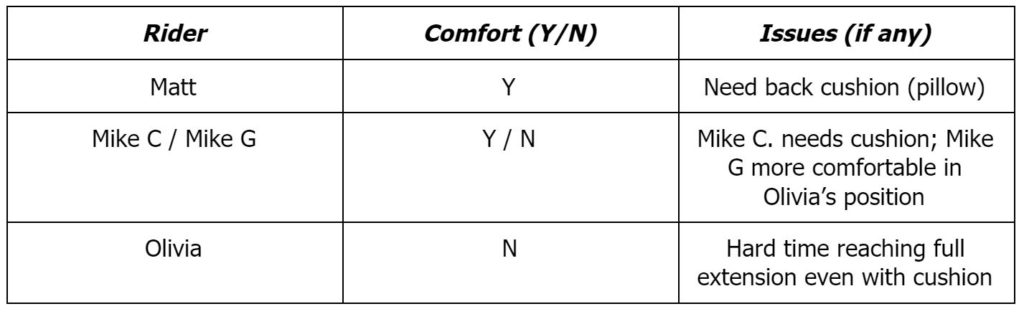
-Mike G. more comfortable in Olivia’s position, but could still ride in his if necessary
-Matt and Mike C. are comfortable in their own position, but just need back cushion to ensure they can reach the full extension of the pedals
-For everyone, the seat does not offer enough back support and thus puts too much pressure on the abdominal muscles. This makes the bike uncomfortable after long periods of riding, especially when strenuous (ex. uphill riding)
Test D2: Speed of Adjustment
Date:
Purpose: -To ensure adjustability mechanisms can be set in varying
positions quickly and effectively, with minimal effort, as well as
full rider changes.
Procedure:-Start with seat locked in forward most position, use wrench to
loosen bolt and move seat to middle position.
-Continue to manipulate seat position in accordance with the
chart below.
-For each manipulation, have rider get in and out of vehicle,
with full harness
Results
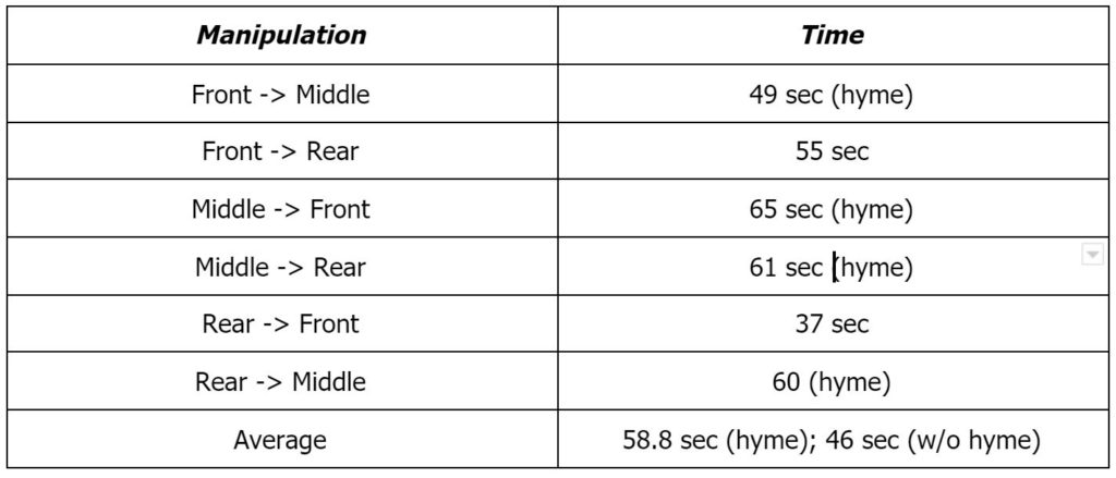
-Carriage and longitudinal tie rod bolts needed to be unscrewed and adjusted for each test, with tests going to and from the middle position also needing hyme joint adjustments to ensure steering calibration.
-Team is satisfied with the adjustments (with and without hyme joint adjustment) taking under one minute