Design

The design process for this project is ongoing. Below you will find variations of the design in chronological order of development and release. Continue to check back for updates or see monthly updates for an itemized list of recent progress updates. Thank you for visiting.

Figure 1. General Concept Diagram depicting features intended to be included in design to meet design controls.
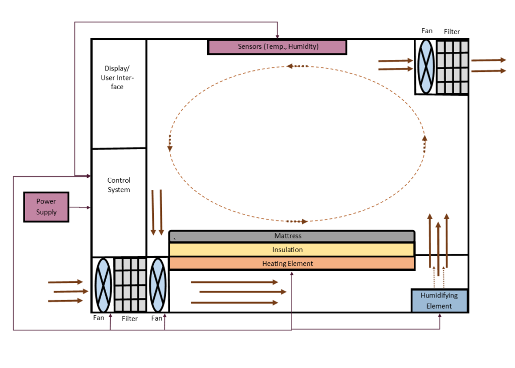
Note: The arrangement of features is subject to change as design solutions are being developed and selected. Oct. 2022
Figure 2. Alternative Solution 1 Sketch. A rectangular prism with a transparent chamber for the infant bed and an enclosed portion to the left and underneath to house the electrical equipment, feedback controls system, and alert system. Heat is generated with a custom resistive wire heating pad located underneath infant bed. Humidity is controlled by an ultrasonic piezoelectric water atomizer located underneath the infant chamber in a water reservoir. Fans and vents are used to move air through the infant chamber. Nov. 2022
Figure 3. Alternative Solution 2 Sketch. A rectangular prism with transparent windows to view the infant bed. Electrical equipment, feedback controls system, and alert system are enclosed to the left and underneath the infant chamber. Located in the back wall is a nichrome coil wire heater and insulation. Underneath the chamber is an evaporative humidifier in a water reservoir and fans with vents to the chamber to move air. Nov. 2022
Figure 4. Initial 3D model of prototype design. A rectangular prism with a transparent plexiglass infant chamber, an aluminum base, and an aluminum back wall. Nichrome coil wire heater is located in the back wall. Water reservoir with ultrasonic piezoelectric water atomizer and intake fan-filter complex are located in the rear of the base. Vents allow air and humidifying mist to the infant chamber. Fan in the top, front corner exchanges air with external environment. Handles are located on each side to move the device. Dec. 2022
Figure 5. Controls System Block Diagram. Power is supplied to all the component with a 12 V battery. An Arduino micro connects our sensors, actuators, and audible/visual alerts. Dec. 2022