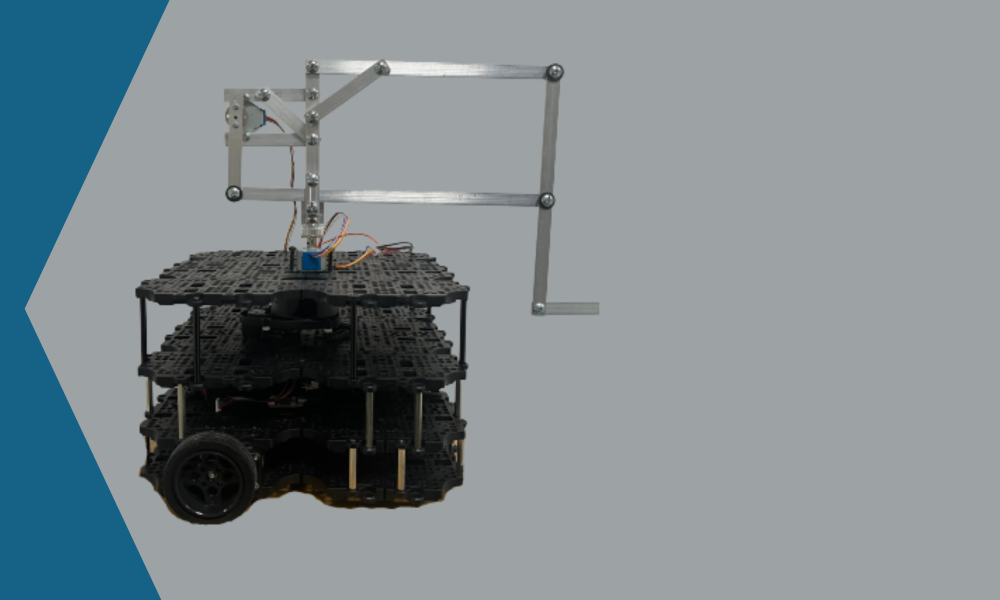
In order to be able to control the robot arm, a circuit needs to be designed that will allow for proper interfacing between the different components, as well as keep the entire system powered at all times. The components that require interfacing for input or output are the stepper motors, as well as the distance sensor. This interfacing must be done with the raspberry pi, which must be powered along with all other components.
One of the reasons that the raspberry pi was chosen for this project is its easily accessible and controllable GPIO pins. These pins can very easily be controlled through scripts or programs running locally on the raspberry pi and can be used as outputs to control the stepper motors as well as inputs to read the results from the distance sensor. There are 40 GPIO pins on the raspberry pi that are available for use, but some of them are reserved for things like power and ground pins. However, there are plenty of pins available for what this project requires.
The first task to be addressed is powering the entire system. The TurtleBot has a battery as well as some power management which gives a 5 V and 12 V rail for use. All components being used here only require 5 V to operate properly, so it is possible to put all components, including the raspberry pi, in parallel on that 5 V rail. This does not work as well in practice, however, due to large current draws from the stepper motors and distance sensor. These current draws make the voltage slightly less than 5 V, due to the internal resistance of the battery and power management system. This is a problem for the raspberry pi, which will throw several low-voltage warnings when operating in this state. Due to this, the 5 V source was dedicated to the raspberry pi and the 12 V source would be used to power the other components. In order to do this, an LM7805 Voltage Regulator was used to limit the voltage to 5 V. A 10 uF capacitor and a 1 uF capacitor were placed between the input and ground as well as output and ground respectively to allow for a more robust and stable 5 V output. This creates an effective 5 V source which all components except for the raspberry pi use.
The next task to be addressed is properly controlling the stepper motors, however, due to the fact that the stepper motors are identical only one control system needs to be designed. The 28BYJ-48 Stepper Motor is very popular among hobbyists therefore its use is very well documented. This allowed for the GPIO pin configuration to be easily decided since it could be programmatically changed as necessary. The main issue that needed to be addressed was the current requirements of the motor. Raspberry pi GPIO pins are not designed to handle large current outputs, therefore a supplementary component is required. The ULN20030A is an IC designed to address the issue of current delivery through the use of Darlington Transistors. When one pin is set high from the GPIO pins, current flows through a corresponding pin on the other side of the chip. This allows for easy step control for the motors while not damaging any components. Two of these chips are necessary since there are eight pins required for the two stepper motors and only 7 terminals on the ULN2003A.
The last task is properly interfacing the HC-SR04 Distance Sensor with the raspberry pi GPIO. The input of the sensor is rated to operate at 5 V, which allows for the use of the 5 V source from earlier. The issue that needs to be addressed is the voltage rating of the raspberry pi GPIO as input pins. The raspberry pi is rated to handle up to 3.3 V, so a voltage divider must be created to reduce the output voltage of 5 V to something under 3.3 V. A goal of 3 V was selected in order to allow for the raspberry pi to easily detect the input while also remaining fairly far from the limit of 3.3 V. Two resistors were selected, with values of 330 Ohms and 470 Ohms respectively, were used to create a voltage divider with a voltage output of 2.94 V. This is sufficient for the sensor to properly interface with the raspberry pi and be used to measure distance.
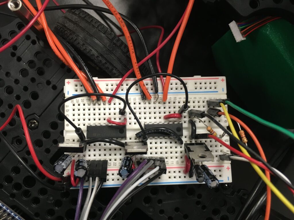
As stated earlier, all of these systems need to be working simultaneously and therefore need to be combined into one large circuit. The voltage control, stepper control, distance sensor control, and all of the interfacing with the raspberry pi GPIO can be seen in a full circuit diagram in Figure 13.

Fig.13 Circuit Diagram
During a demonstration of the system, an issue occurred where, after performing the demo for a while, the 5V source would drop its voltage to around 2.5 V and remain there until the demo program was terminated. The issue would come back after starting the demo up again, but the longer the wait time, the longer it took for the issue to resurface. It was determined that the LM7805 Voltage Regulator was overheating, which was occurring due to the power required to dissipate the extra voltage at the operating currents. One solution investigated was attaching a heat sink onto the voltage regulator, so it would more efficiently dissipate heat and continue functioning. Another solution was to insert more voltage regulators, since the 12 V source could handle the current draw it was only necessary to split the workload on the regulator, and this would be done by giving each stepper motor and the ultrasonic sensor its own 5 V source from a voltage regulator. The latter solution was selected due to the fact that there were many more voltage regulators available since they came in a pack of 25. The circuit diagram in Figure 13 is still accurate, there are just two more LM7805 voltage regulators and each component has its own 5 V line.
Final Circuit