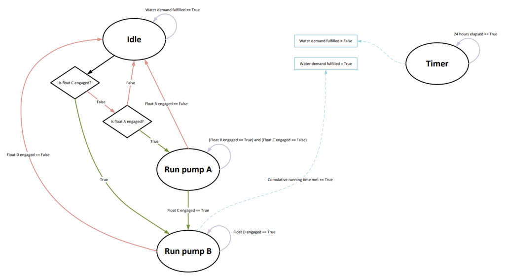
The general layout of functions of the code is illustrated below in Figure 1. Idle marks the initial setup of the system when no water is in either of the tanks. From here, each sensor will be checked for engagement and based on the output, the code will proceed accordingly. A timer will also be coded into the system to ensure the water is pumped for an allotted amount of time out of every 24 hours.
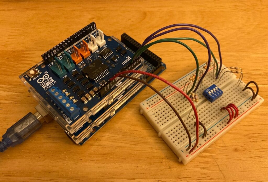
An arduino, relay shield, motor shield and sensor board will be utilized as shown in Figure 2. In order to account for the 2 setups of the teams’ design, the relay shield will control the on and off of the pumps while the motor shield will control the parameters of the valve. A bread board will also be used to connect the 4 float switch sensors of the buckets in order to have a fully functioning system that is able to regulate itself.