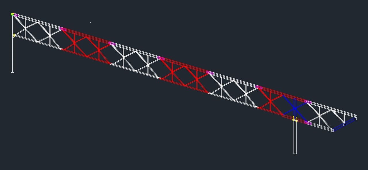
Monthly Archives: October 2016

Update 5

Full length drawing

Design Update

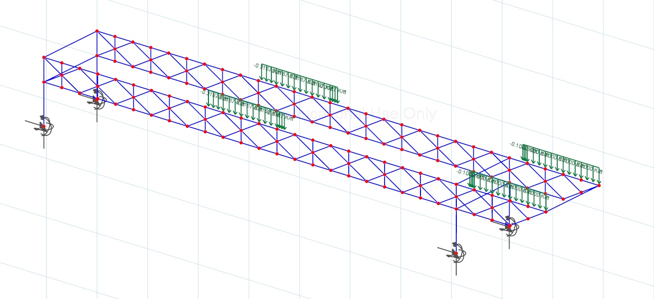
The team has developed a 3D model of the tentative bridge design in order to better manipulate the dimensions of individual members and design connections. The model also allows the team to better visualize the depth of each material type and how they interface with each other. Lateral bracing and support design are also well under way and will be mentioned below.


connection

Connection Update

The team has been exploring a variety of possibilities for connections. Depicted is a possible sliding connection solution at the interface of the top and bottom truss members. Compression members will be connected with telescoping box tubing, and the tension members will potential utilize a version of the connection above. This type of connection allows the weld to bear the majority of the forces and could minimize potential bolt failures. The cantilever side will have some unique connections due to the geometry that are also being considered.


lateral

Lateral Bracing Update

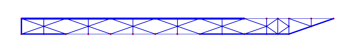
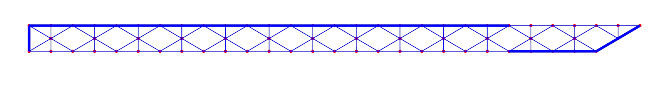
Several lateral bracing configurations and materials have been considered in order to resist the lateral load test and minimize the weight of the bridge. Potentials designs are being modeled in visual analysis and will eventually be added to the CAD model.


Supports

Support Design

The team has also been at work modeling potential designs for the supports. The supports must hold the weight of the bridge and add loads, and also resist sway during the lateral loads tests. Above is one of the potential support designs. When the supports are finished with selected materials, they will be modeled in 3D in CAD and added to the overall design drawing.

Update 4

3DVA

Design Selection

From the three preliminary designs the team began to move forward with design selection. Visual Analysis software was used to determine the deflection and weight of the bridge under different load cases. From the analysis, the team determined that the aggregate deflection for design #4 was 0.577 in. with an estimated weight of 200 lbs. These values allow the team to rank the bridges and determine which design would perform best at the competition. Design #4 as stated above was selected as the most optimal design. A Gantt chart and budget were created and will be used going forward to monitor progress and expenses. The next step is to start thinking about truss integration with the supports and lateral bracing of the bridge.

Update 3

alt design 3

alt design 4

Fundraising Update:

Fundraising for the project is well under way! The team did some research and utilized donation contacts from last year’s team to reach out to a variety of companies. Companies were asked for monetary donations to support the TCNJ chapter of The American Society of Civil Engineers and the corresponding projects. Among the many other companies, the ASCE Central Jersey Branch and the American Institute of Steel Construction were also contacted. The sponsorship page will now be active and display the logo of companies who have graciously donated to the project.

Design Update:

The Quarterly Report is complete and will present each of our design alternatives with a breakdown of total weight, number of connections, and maximum deflection as calculated by Visual Analysis (pictured above are two of the finalized design alternatives). From these design alternatives a final design will be selected. The next step will be to complete the footing design and the connection design.

Update 2

update2.1 update2.2 update2.4

The team has been using Visual Analysis to model possible truss designs for the bridge. Above are pictured a few of the variations based on the cantilever (AB footing) design. In addition to these designs, various symmetrical bridge (AC footing) designs have been developed and will be modeled and tested. Adjusting materials and geometry, and then testing for deflection and stresses in the members will allow the team to select the best possible design. Once a main truss design is tested and selected, lateral bracing and footing design will be follow.