
Digital Logic Process Controller
A digital logic controller (DLC) was designed for TJT’s process control, namely, the operation of the pumps and solenoid valves. The design begins with the device requirements for therapeutic effects.
In order to acheive theraputic effects, the device must apply heat to the hand for 6 minutes and cool the hand for 4 minutes three times, for a total theraputic cycle of 30 minutes.
The required operational states, derived from design specifications, are:
- Standby: All gates closed, all pumps off, but heating and cooling remain active to maintain reservoir temperatures
- Heat: Pumps on, open gates 1 and 3 to allow hot water to enter the hand interface
- Cool: Pumps on, open gates 2 and 4 to allow cold water to enter the hand interface
- Empty Bladder: Pump 2 on, close gates 1 and 2 while leaving either gate 3 or 4 open (depending on the current operational state) to remove all water from the bladder.
- Startup*: Heat and Cool reservoirs to 42 and 16 degrees centigrade in preparation for therapy
*Startup only occurs at most once per treatment cycle and is included in the microprocessor start-up sequence
The transitions between these states, and therefore the timing of the device, are controlled by the following binary input signals:
- Pd = 1 : Bladder pump out done
- B = 1 : Preheat has been completed and the start button has been pressed
- Time_h = 1 : Hot cycle time has elapsed
- Time_c = 1 : Cold cycle time has elapsed
- Time_d = 1: Total treatment cycle time has elapsed
- S = 0 : No safety issues have been detected
The valves and pumps were all labeled as follows.
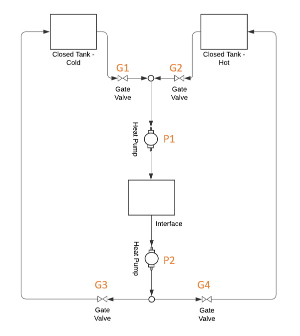
Process control diagram with output binary state variables indicated in orange
These state outputs are combined to create a single binary word representing the device’s current operational state. For pumps, zero represents no water flow, while for gates, zero represents a closed valve.
| 0 | 0 | 0 | 0 | 0 | 0 |
| Pump 1 | Pump 2 | Gate 1 | Gate 2 | Gate 3 | Gate 4 |
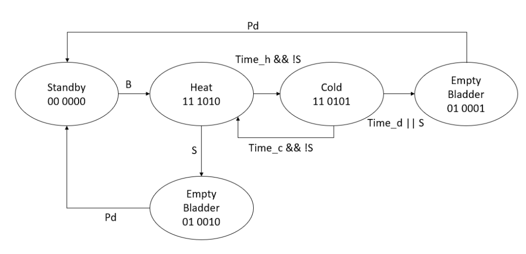
All of this information was then combined into a single state diagram derived from operation specifications.
The standard DLC design algorithm, assuming a reset and the set signal cannot be high simultaneously is shown below.
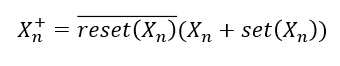
This equation, applied to each of the states, reduces to the following state equations:
 P1 = (!S)&&(!time_d)&&(P1 || B);
 P2 = (!Pd)&&(P2 || B);
 G1 = (!time_h)&&(!S)&&(G1 || B || (time_c && !S));
 G2 = (!time_c)&&(!S)&&(!time_d)&&(G2 || (time_h && !S));
 G3 = (!(time_h && !S))&&(!Pd)&&(G3 || B || (time_c && !S));
 G4 = (!(time_c && !S))&&(!Pd)&&(G4 || (time_h && !S));
These equations were then transferred to Xilinx Vivado for logic verification. The resulting waveform can be seen below.
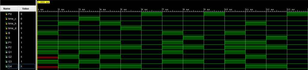
The waveforms, compared against the state diagram above, confirmed that the digital logic controller operates as expected.
Temperature Controller
Overview
Reference controller, etc.
Sensors
Thermistor
Actuators
Peltier and Resistive array
While device construction is delayed by TCNJ’s COVID-19 Policies (see https://emergency.tcnj.edu/covid-19/ ) the documentation of the design project is being refined. Please check back in a few days.
Updated 4/1/2020