
System Overview
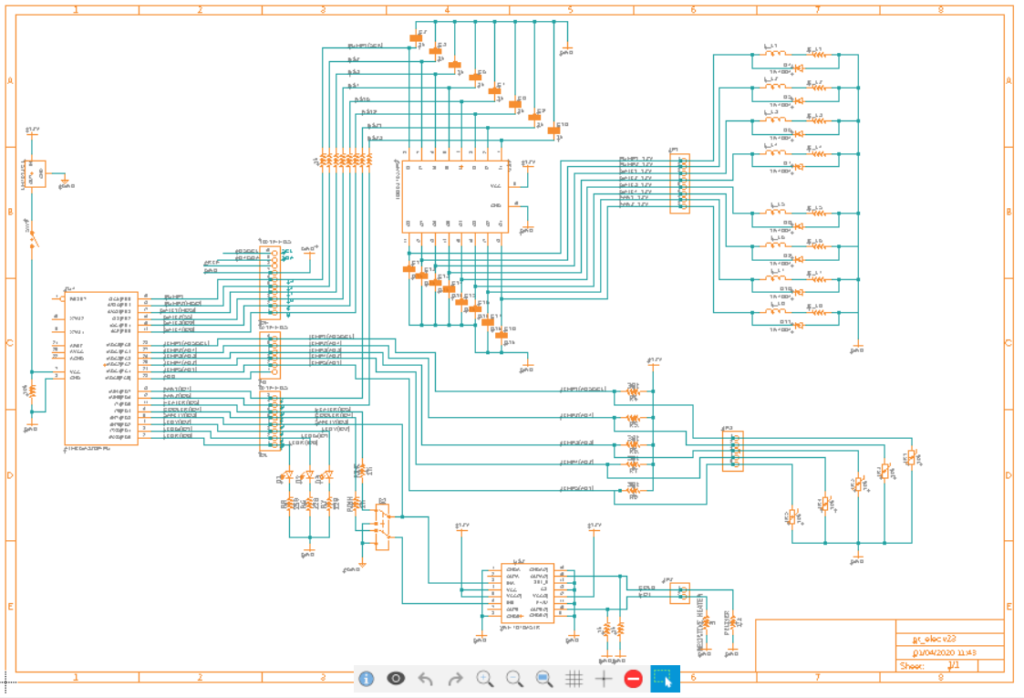
The electrical design for TJT began at the system level. Using the electronic design automation software EAGLE, the team transformed a high-level functional block diagram into an electrical schematic with discrete components and ICs.
- The Arduino ATMEGA328PU IC model was taken directly from ArduinoUno open-source EDA files to accurately represent the microprocessor’s I/O pins.
- The second column of jumper pins represents off-board components
- Created two custom components, VNH7070ASTR and TD62783APG
- Pending the completion of the flexible hardware prototype (i.e. protoboard or breadboard), the EAGLE schematic will be adapted to allow the realization of a prototype PCB
Below, we will go through the electrical subsystems one by one.
Arduino Uno
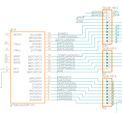
Function: As development progressed it became clear that the Arduino Nano did not have enough GPIO pins to support the project. The choice of MCU was easily changed to the more readily available Arduino Uno. It is also noted that with the Uno the design uses all but one of the analog and digital I/O pins (Analog In 0 remains open).
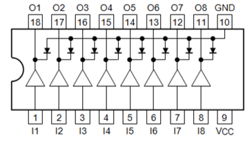
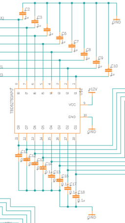
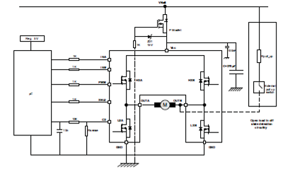
Load Switch (TBD62783APG)
Technical Specifications:
- PWR SWITCH N-CHAN 1:1 18DIP
- Voltage – Load (Max) = 50V
- Current Output (Max) = 500mA
- Features: Clamp Diode for Switching Inductive Loads
Function: Due to the relatively high power actuators used in the process control, the microprocessor is unable to drive loads. Therefore, a switching mechanism, controlled by the microprocessor, must connect and disconnect the loads from an external 12V power supply. All eight switches are used. If we were able to increase the number of load switches, the design would support more DC fans for improved airflow and component thermal regulation.
DIP-18 Package 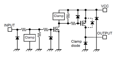
TBD62783APG equivalent circuit
Flywheel Diodes (1N4001)
Technical Specifications:
- Non-Repetitive Peak Forward Surge Current: 30A
- Working Peak Reverse Voltage: 50V
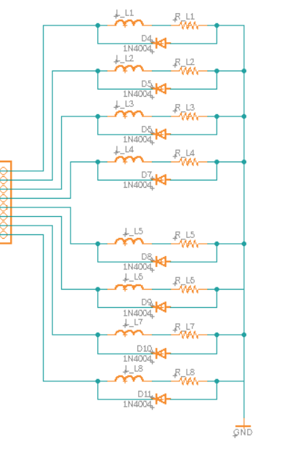
Function: The actuators controlled by the microcontroller are responsible for controlling the device’s process. These actuators, four electric solenoid valves, two diaphragm pumps, and two DC fans are inductive loads. As a precautionary measure, to prevent voltage spikes across the inductor from an interrupted power supply (i.e. flyback), designated flyback diodes have been placed at each of the inductive loads. Although the TBD62783APG IC includes inductive switching features, the diodes were included for redundancy.
Bypass Capacitors
Technical Specifications:
- 8x 0.1 uF Ceramic Capacitors (Load Switch Output)
- 8x 1uF Ceramic Capacitors (Load Switch Input)
Function: Load switching produces a transient response in current and voltage waveforms throughout the system. To protect the system from rapid changes, bypass capacitors are used to produce a low pass filtering effect which removes high-frequency components from the transient response. These capacitors ensure smooth transitions. Capacitance values are taken from the TBD62783APG application notes.
LED User Interface (UI)
Technical Specifications:
| UR502DCRed LED | G502DC Green LED | L-7113YT Yellow LED |
| Operating Forward Current: 20mA Typical Luminous Intensity (@ If = 20mA): 800 mcd | Operating Forward Current: 20mA Typical Luminous Intensity (@ If = 20mA) : 120 mcd | Operating Forward Current: 20mA Typical. Luminous Intensity (@ If = 10mA): 40 mcd |
LEDs were chosen based on availability. Yellow and Green wired in series with 220 Ohm current limiting resistors. Red wired in series with 250 Ohm current limiting resistor (to reduce luminous intensity).
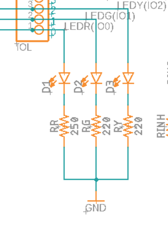
Function:
- Serve as the primary user interface with the patient.
- Red: Error/End Treatment
- Yellow: Treatment in Progress
- Green: Ready/Standby
- Blinking Green: Pre-Heating
Safety Switch Feedback Network
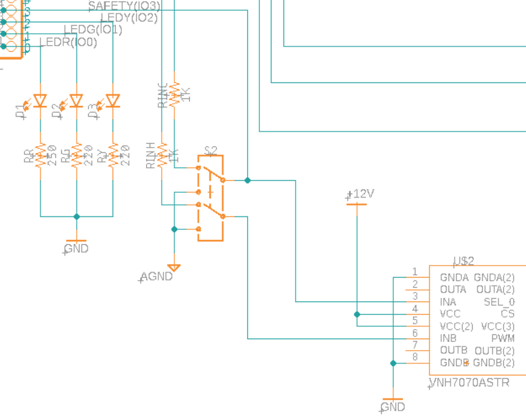
Technical Specifications:
- TL2205OABPBB
- DPDT On-mom
- Current Rating (DC): 100mA
- Voltage Rating (DC): 30V
Function: When the user chooses to end treatment, for any reason, emergency or otherwise, the DPDT manually grounds the input into the high current IC controller. There is a digital input connected to one of the input pins which compares the value outputted by the Uno to the value being read by the IC controller. If a discrepancy appears, the switch has been thrown and the DLC moves the device back to standby. In this situation, only one of the IC Controller’s inputs must be sampled to detect the switch state due to the mechanical Double Pull Double Throw nature of the switch.
Power Temperature Controller
Technical Specifications:
- VNH7070ASTR Half Bridge (2) 16-SOIC Motor Driver
- Current Output = 15A
- Voltage Supply and Voltage Load = 4V – 28V
Function: This IC acts as the load switch for the high power heating array and Peltier module (~6.5A typical). Normally used for motor control in an H-Bridge configuration, the IC includes a PWM speed control signal. However, upon inspection of the datasheet, it became clear that the PWM speed control relied on a range of frequencies (0-20kHz) rather than true pulse width modulation. For the Arduino Uno, the only frequency of PWM available is at discrete values (490Hz or 980Hz). The method for speed control used in the IC is to connect the PWM signal into the gate of the low-side transistors of the H-bridge. As the switching frequency increases, the more power is diverted away from the output to ground. To overcome this issue, the heating array and Peltier units will be operated using an on-off control scheme, omitting PWM control in favor of direct microprocessor control over the two input pins. It is possible to control both modules independently by operating the IC in a half-bridge configuration.
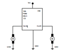
Half Bridge IC Operation 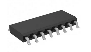
SOIC-16 Package
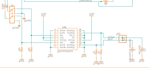
EAGLE VNH7070ASTR Wiring Schematic
Power Management
Technical Specifications:
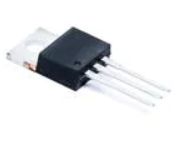
- LM7812CT/NOPB
- Linear Voltage Regulator
- Output Voltage: 12V
- Output Current: 1A
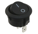
Technical Specifications:
- SPST Rocker Switch
- Current Rating (AC) = 20A
- Voltage Rating (AC) = 125V
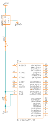
Function: The power management system for the Arduino Uno consists primarily of an on/off SPST rocker switch in series with a 12V linear voltage regulator which is regulating the power coming from the supply bus. The voltage regulator is a precautionary measure to ensure that during load switching the microprocessor sees no change in input voltage. The regulator will be attached to a small heat sink and cooled appropriately.
Component Verification
While device construction is delayed by TCNJ’s COVID-19 Policies (see https://emergency.tcnj.edu/covid-19/ ) the documentation of the design project is being refined. Please check back in a few days.
Updated 4/1/2020