
The data is transmitted between the computer and the master board through a UART interface. The UART interface consists of the 2 wires attached to pins P11 and P9 on the master board. The UART to USB converter turns the 2-wire interface into USB so that it can be connected to the computer for data transmitting and receiving. There are 2 other wires that are connected to USB (one is connected to the master board and the other is connected to the slave board). These wires provide power for the boards. The computer provides 5V to each of the boards, and each board has a voltage regulator that changes the 5V to the 3.3V that the board can use.
The SPI interface consists of the 3 wires used to connect the boards. For these 3 wires, the pins used on the master board are the same as the pins used on the slave board because of how SPI is connected as shown below. All the wires are unidirectional. The first is MOSI (master-output-slave-input) to transmit signals from the master board to the slave board, the second is MISO (master-input-slave-output) to transmit signals from the slave board to the master board, and the last is for the clock which is created in the master board and sent to the slave board.
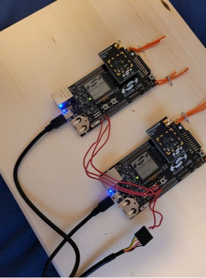
The radio boards are each connected to the corresponding board (one to the master board and one to the slave board) and each radio board will have an antenna for communication with the tags. Shown below is the hardware powered on.
Components
- 2 EFR32xG Pro Kits
- Multiport USB cable
- USB to UART Serial Converter
- Wire
- Tags