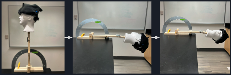
Testing Frame
Through the verification and validation testing of the Epley Maneuver System, we were given the opportunity to create a complementary tool exclusively for testing this device and ensuring that it works as stated. The frame is easily adjustable and manipulated to mimic the position of a person performing the Epley maneuver.

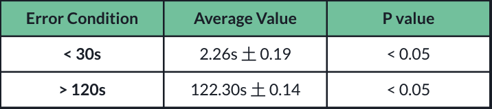
Design Input 1 – Verification
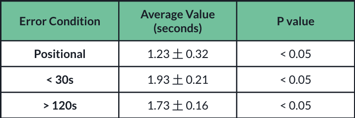
- Device was positioned so error conditions in position and time occur
- Similar process to that of Design Input 3
- Device positioned just outside of target angle so errors would occur
- Difference between this angle and the target angle recorded
- No resolution for this spec
- Device is still able to accurately measure errors within the range of 10 to 11 degrees
- One tailed one sample t-test used

- When time error occurred also recorded
- < 30s and > 120s
- Device reported errors within the expected time frame
- One tailed t-test compared with 30s and 120s respectively
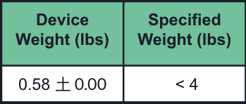
Design Input 2 – Verification
- Device weight was 0.58 lbs
- Weighed 3 times and averaged
- One tailed one sample t-test done
- Compared to max weight of 4 lbs
- P < 0.05
- Device weight significantly different than 4lbs
- Passes verification
Design Input 3 – Verification
- Simulated Head used to record different angles
- 100 data points recorded
- 0, 90, 180° on x-axis
- -50, 85, 245° on y-axis
- 65, 145, 225° on z-axis
- Difference between target angle and recorded angle taken
- Angles chosen 20 degrees past range of Epley Maneuver and middle
- Wilcoxon test used
- Data not normally distributed
- Compared to see if difference was less than 1
- All angles pass with p < 0.05
- Device is able to measure target angles within 1 degree

Average difference from target angle with error bars and target values (p < 0.05)
Design Input 4 – Verification
- Device positioned or timed into different error conditions
- Utilizing simulated head similar to design input 3
- Time taken for feedback to be administered recorded (n = 10)
- Values averaged
- One tailed one sample t-test performed
- Compared to hypothetical mean of 3 seconds
- Less than 1/10th the time per step in the maneuver
- Passes verification for design input 4
Design Input 6 – Verification
- Baud rate of 9600 confirmed to be used in Arduino
- Corresponds to 960 bytes/s
- 7.68 kbps
- Fails verification for design input 6
- Due to the nature of how Arduino transmits data this was unable to be reached
- Using a different microcontroller chosen in the future would fix this
Design Input 7 – Verification
- Device was powered on either for five hours or until battery died
- Power lasted for the full five hour period
- Device passes verification for design input 7
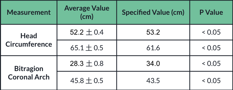
Design Input 8 – Verification
- Minimum and maximum adjustable values measured (n = 3)
- Done for head circumference and bitragion coronal arch
- One tailed one sample t-test performed for minimum and maximum values
- Device passes verification for design input 8
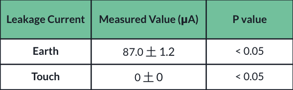
Design Input 10 – Verification
- Leakage current testing done in accordance with IEC 60601
- Minimum earth leakage current: 5 mA
- Minimum touch current: 0.1 mA
- 5 Measurements taken each
- One tailed one sample t-test performed

Body model used to test touch current