
Week 10-12 (April 5th-April 26th)
For the past 3 weeks, the hip implant and its parts has been finalized after evaluating the printed version of it. The stainless steel prototype will be done by April 28th. Finite Element Analysis was successful.
Verification Activity for Requirement 1’s Specification:
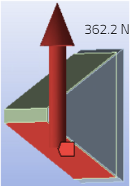
For requirement 1, the point force was calculated under the assumption that the patient weighted 380 lbs. So we took this body weight converted it into the equivalent force in Newtons. The hip joint experiences 1.5 times the patient’s body weight when walking. We looked at the walking force experienced within the hip joint as this is the least impactful cyclic activity. Therefore the static equivalent force from the patient’s body weight was multiplied by 1.5. We assumed then that the this force was equally distributed over the 7 pins to obtain an applied force of 362.2 N
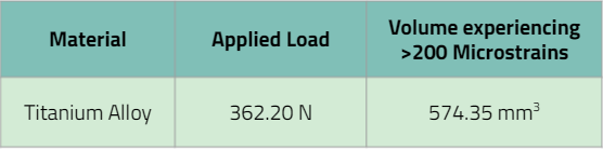
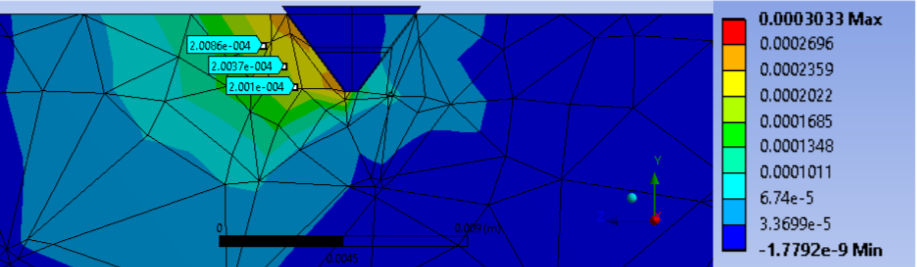
It was observed that the region of more than 200 microstrains edge ran parallel to the slanted face of the pin tip. Our team assumed that this region was homogenous along the face of the pin tip and by utilizing the surface area of the pin face were able to obtain a volume of bone that had more than 200 microstrains. The results of this study are highlighted on the table on the slide. From this study, we were able to conclude that the pin tips were able to induce a region that produced more than 200 microstrains within the surrounding area of bone. While we do not have a volume of bone to compare to as a control, the results of this study are indicates a passed verification activity.
Verification Activity for Requirement 2’s Specification:
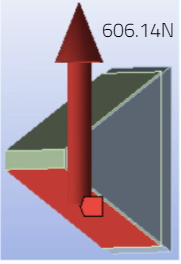
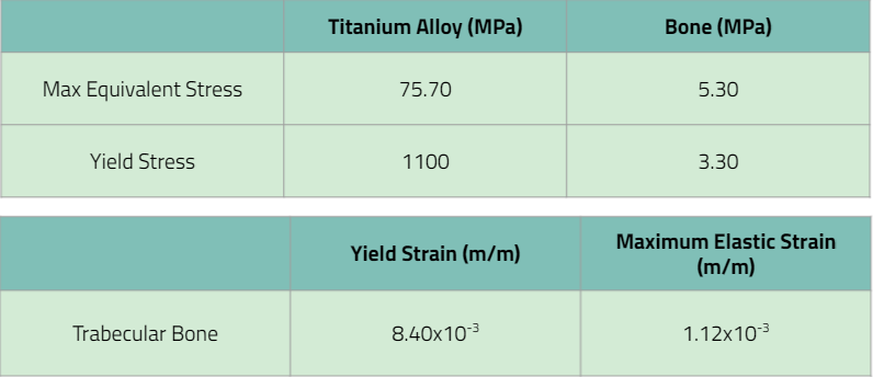
Verification of this requirement was similar to that of requirement 1. Since only 1 pin was analyzed, the total force of 4243N was divided by the 7 pins assuming equal distribution of the force across all pins to give us a force of 606N on 1 pin. This test was done to predict whether the device would be able to withstand the static force necessary in applying the maximum force during stair climbing.
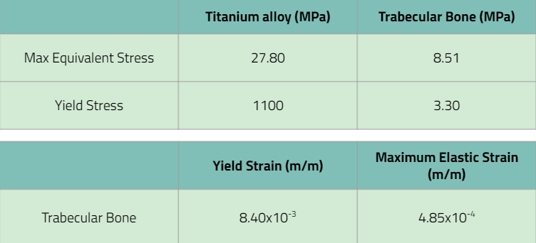
The requirement stated that the device itself must carry the maximum load without breaking, so comparing the maximum stress on the titanium alloy pin to the yield stress, the max equivalent stress of 27.8<1100 which confirms that the device itself wouldn’t break. When analyzing the max equivalent stress of trabecular bone, bone would break. However, this can be a mistake we made in ANSYS where we made bone an elastic material for simplicity. All in all, the verification activity passed.
Verification Activity for Requirement 3’s Specification / Validation of Requirement 3:
To verify the specification for requirement 3, the metal prototype and sawbone used for experimental testing was measured with a caliper to ensure that it followed the specifications. The metal prototype stem anchoring was less than 15cm and the sawbones diameter was greater than 9mm, which means that this device passed the verification activity.
Since the metal prototype had approximately the same measurements as the 3D drawing created in SolidWorks, requirement 3 was validated.
Verification Activity for Requirement 4’s Specification / Validation of Requirement 4:
We were not be able to physically test this requirement due to the fact there are no hydraulic testing frames with the capability to do cyclic testing at the scale we need at TCNJ
Theoretically, an S-N curve would have be created and implemented into ANSYS simulations to illustrate the degradation of the implant over time.
Ideally this requirement would have been validated by comparing cyclic loading behavior to current hip implants on the market
Verification Activity for Requirement 5’s Specification:
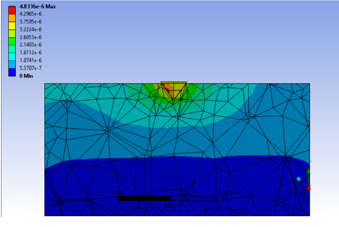
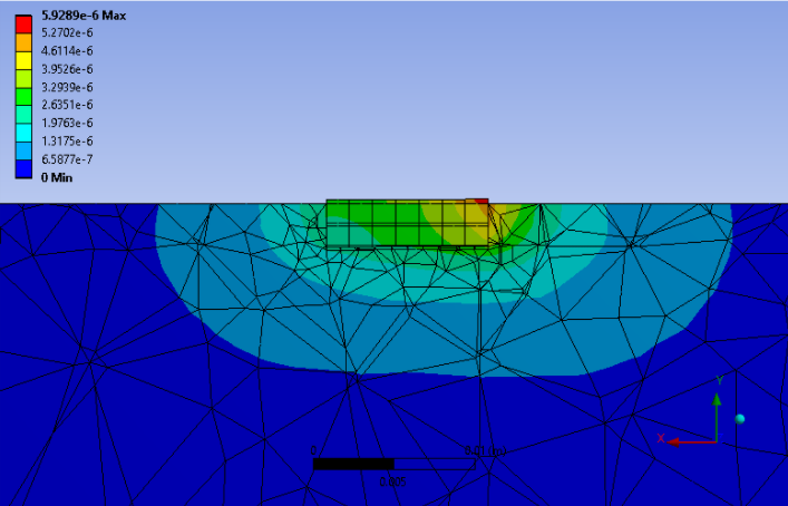
The purpose of requirement 5’s verification study is to verify that the novel implant design will meet the specifications set forth in requirement 5. Similarly to requirement 1, the pin was embedded into a simulated bone block large enough to assume that there is infinite material around the pin at the point of insertion. The applied force was obtained assuming that the 2,250N force that was stated in the specification for this requirement was distributed over the 7 pin tips evenly. The force obtained from this calculation was 321.4 N. The point load was applied on the slanted face of the pin tip as shown on the slide above.
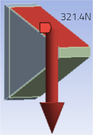
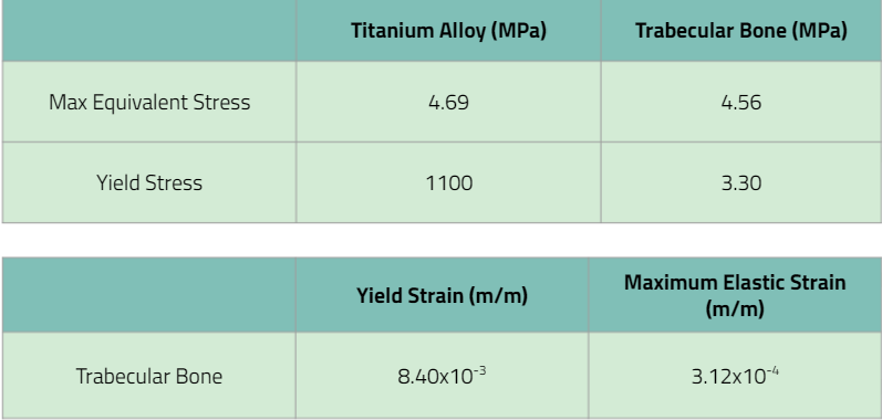
The ANSYS simulation showed that the maximum stress experience within the pin was far below the yield stress of the titanium alloy. It was also noted that the maximum stress experienced was less than that of the Elastic modulus of trabecular bone (1.8×10¹⁰ Pa). The data is displayed in the table above. Since the maximum stress experienced within the bone-pin tip composite is much lower than the young’s modulus of the ideal metal for the implant, the implant will not fail. Based on the results of this study, the implant will be able to withstand the applied load of 2,250N as per the specification of requirement 5. The implant has passed this verification activity.
Verification Activity for Requirement 6’s Specification:
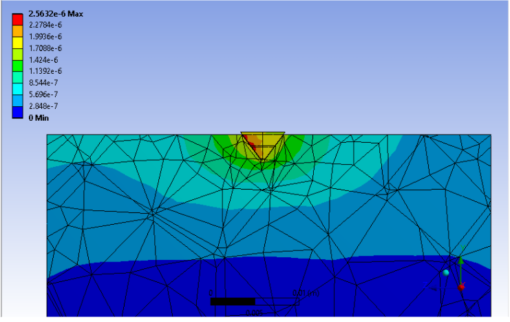
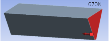
A small scale ANSYS simulation was done to verify this requirement as well, but the force was place on the right side face instead. This was considered sufficient assuming the change in angle theta will be so small that the displacement of the pin during failure will be approximately linear. The required torque was converted to a force using the moment equation and divided by the 7 pins to give us 670N on each pin.
Again. the maximum equivalent stress on a titanium alloy and stainless steel pin were analyzed with stainless steel having a slightly higher stress. Both materials are considered comparable in this study as well. The high percent difference between the titanium alloy young’s modulus and stress on the pin was very high verifying that the device would not break.
Validation of Requirement 1, 2, 5, 6:
If the device passed the verification activity, the device has also been validated
Proper validation would include:
Cadaveric femoral bone implantation by a surgeon
Mechanical testing of this system using a titanium alloy device would validate the requirement
Extra SolidWorks Model:
A SolidWorks design of a cup and a grip was created. The torsional testing machine required a cup to hold the sawbones containing the hip implant and a grip for the machine to grab onto. This was necessary to test one of our requirements:
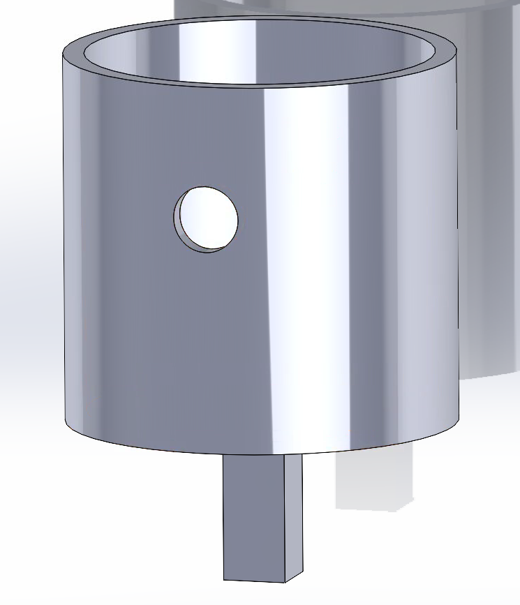
Testing will begin next week once the hip implant, cup, and sawbones are ready.