
Week 7 (October 12th-October 19th)
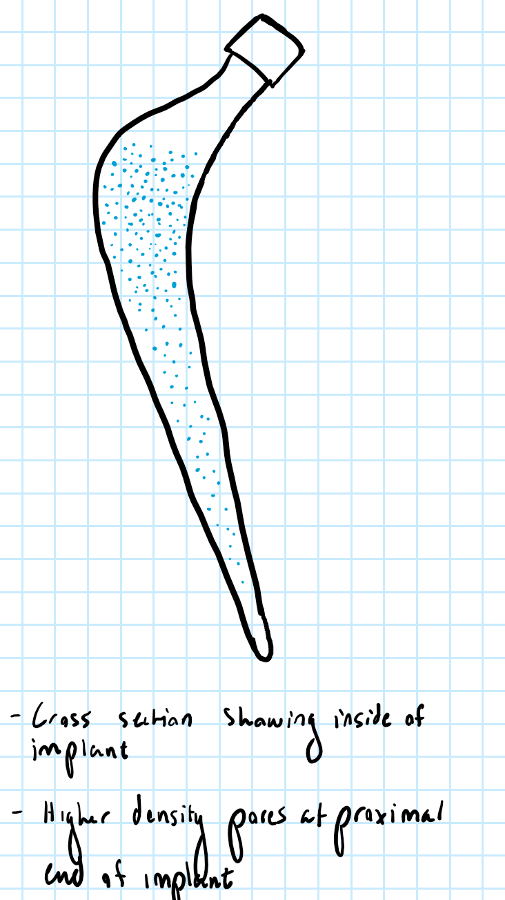
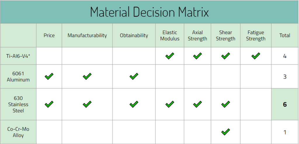
Beginning on October 12, we came up with two design possibilities that included multiple collars and pores to prevent stress shielding. These were preliminary designs, but it built a good foundation of what we want to do in the near future with our designs. It helped the team create even more ideas and we plan to come up with more throughout this month. In addition to designs, we also created a decision matrix to figure out which materials to use for our prototype. This allows us and other people to find a justification of why a type of material was used. Lastly, a safety survey analysis was created for our device to discuss about potential hazards that may come with creating and testing the device.
Design Possibilities:
Week 8 (October 19th-October 26th)
During this week, we took our designs from before and created mechanical changes for the femoral stem. We also annotated each design option so that it is more detailed for clarity.
Design Option 1:
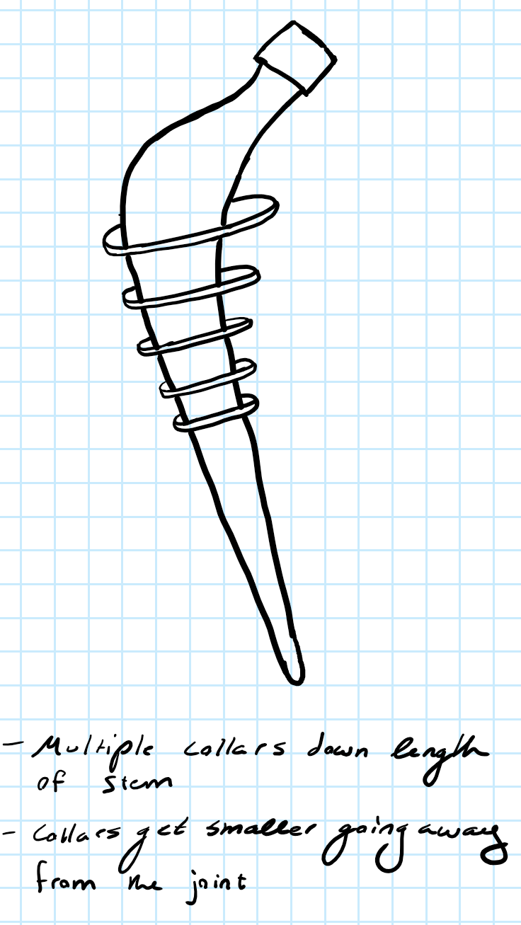
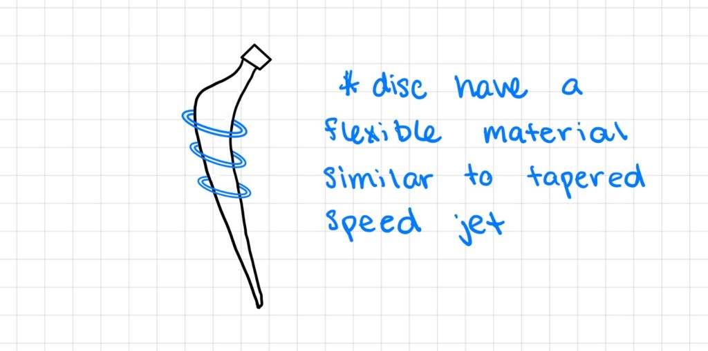
In this first design option, we attached collars to the stem that would decrease in size from the beginning to the end of Gruen zone 1 and 7 to address the most common area of loosening. The collars would be made out of a flexible material similar to tapered speed jet, so that it enables surgeons to put the femoral stem into the femur with no issues. The purpose of this was to increase fixation between the implant and the femoral bone interface, while having the disc come in contact with the bone to redirect the load from the implant to minimize stress shielding.
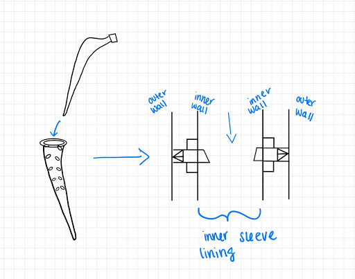
Design Option 2:
Our second design option utilized a pin-ejection mechanism. This design has two main components, a metal sleeve and the metal stem. The metal sleeve is designed to house multiple trapezoidal prism shaped pins. Before the pins are ejected, the points of the pins are meant to be flush with the outer wall of the sleeve so that the pins do not impede on surgical implantation. Once the metal sleeve has been placed, a secondary metal stem will be inserted into the sleeve. As the metal stem goes down the length of the sleeve, the stem will push on the ends of the pins and force them through the holes in the walls of the sleeve. The pin’s tip would then would push into the bone beside the sleeve. The metal stem would be designed to fit snugly into the sleeve so that there is minimal room for micro motion between the sleeve and the stem.
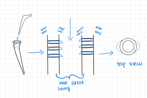
Design Option 3:
This design’s mechanism is similar to design 2, however, instead of trapezoidal prism shaped pins, they are discs that will come out of the sleeve. The discs will go from the beginning and end of Gruen zone 1 and 7 of the femoral stem to focus on the major stress shielding area.
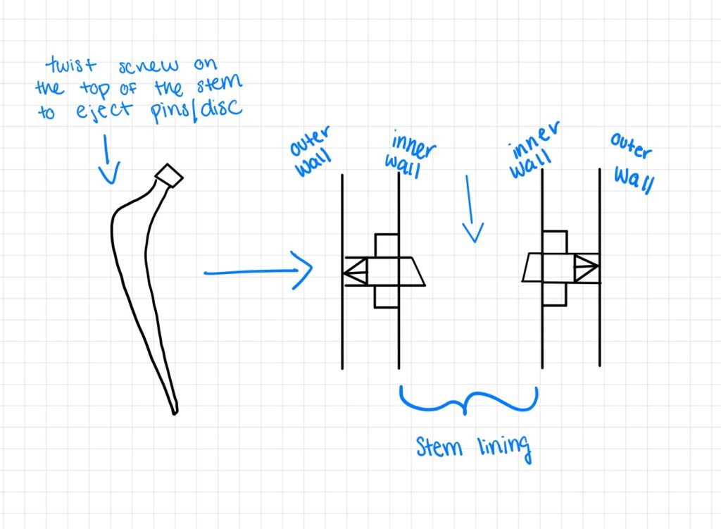
Design Option 4:
Our fourth design is similar to that of the two previous designs, however, a sleeve component will not be used in order to minimize possible corrosion. In this design, a screw will be put into the femoral stem and when twisted, will eject the structural supports (pins). Here the pins are housed in the stem lining and once implanted and screwed in, the pins will eject to apply load into the bone. Overall these designs help plan to minimize stress shielding and increase fixation by redirecting the load into the bone as opposed to the implant.
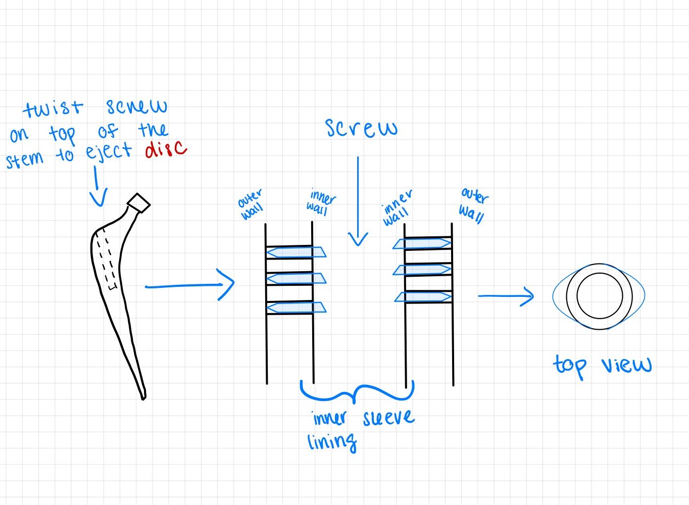
Design Option 5:
This design is similar to design 4, however, instead of the pins with a trapezoidal prism at its tip, it will be disc shaped.
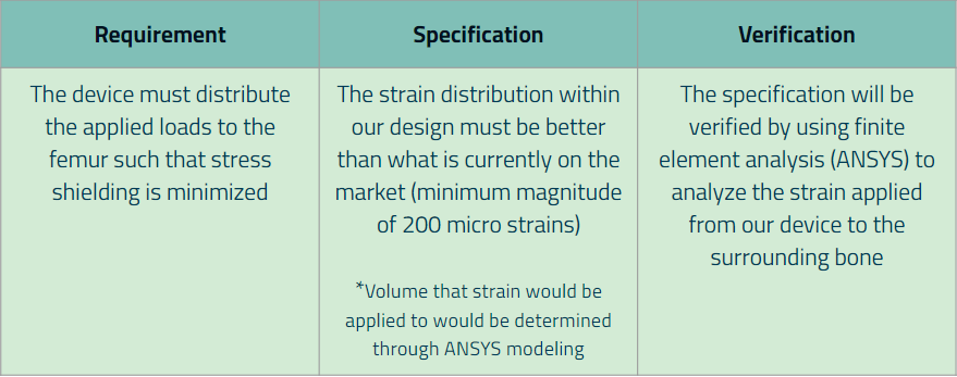
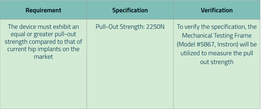
Additionally, for each major requirement and specification that was created, we wrote down the method of how the specification values will be verified. Below are our finalized requirements (along with its specification):
Requirement 1:
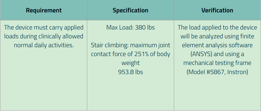
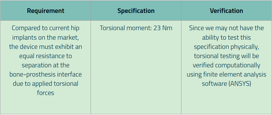
Requirement 2:
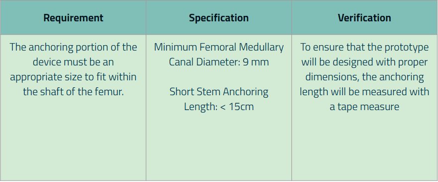
Requirement 3:
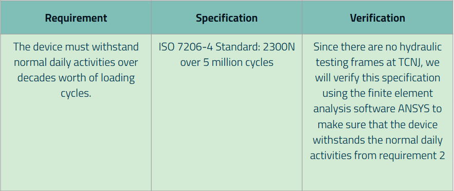
Requirement 4:
Requirement 5:
Requirement 6:
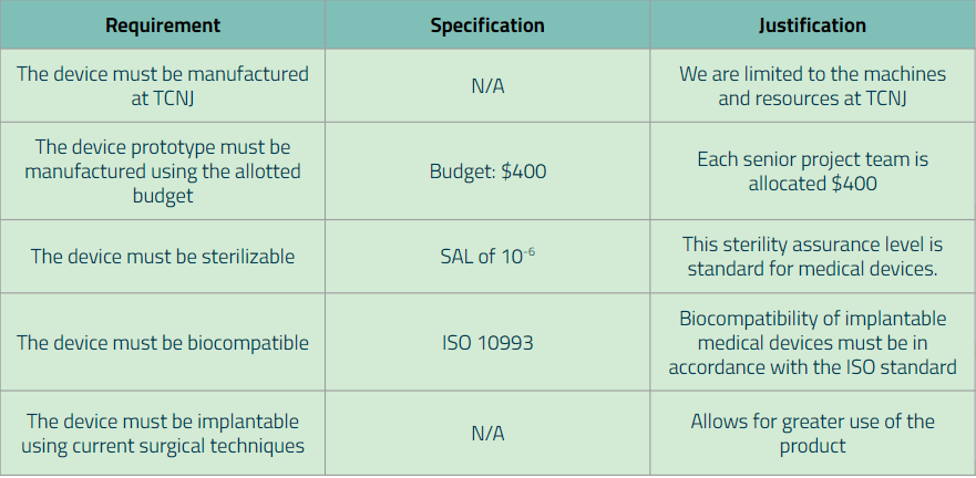
Additional Requirements:
Week 9 (October 26th-November 2nd)
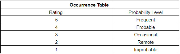
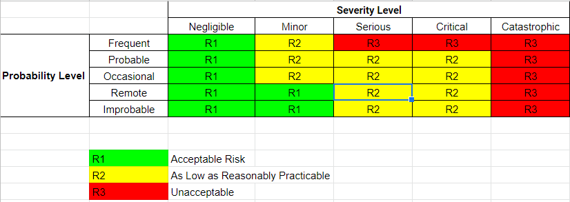
During this week, our team worked on creating a risk analysis table where it documents both the intended use and foreseeable misuse of the hip implant. Additionally, it also identifies the known and foreseeable hazards that come with the use of the device. By creating this table, it helps predict the severity and occurrences of each hazard, which can prevent future injuries to patients. Below are our severity, occurrences, RPN (risk levels), and risk analysis table:
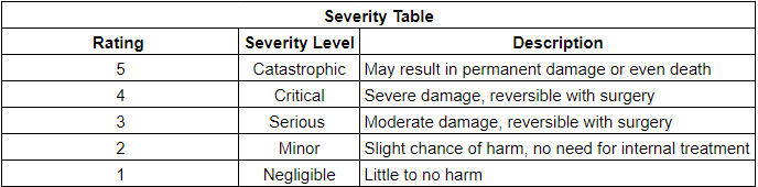
Risk Analysis Chart:
| Hazard | Hazard Event | Harm | Severity | Occurrence | Total Risk (RPN) | Mitigation |
| Shattered Bone | High Impact Events | Damage to Surrounding Muscle or Nerves, Internal Bleeding | Catastrophic | Improbable | R3 | Provide Physician with clear precautions for patient on how to avoid hazard |
| Infection (Not from Surgery) | Bacteria enters Blood Stream | Necrosis, Amputation | Critical | Remote | R2 | Proper sterilization and minimize gaps in parts of the implant |
| Implant Fracture | High Impact Events | Revision Surgery | Critical | Occasional | R2 | Provide Physician with clear precautions for patient on how to avoid hazard |
| Bone Fracture | Falls, Osteoporosis | Possible Muscle Damage, Nerve Damage, Muscle Spasm | Serious | Occasional | R2 | Provide Physician with clear precautions for patient on how to avoid hazard |
| Implant Dislocation | Crossing Legs, Bending over 90 Degrees, Squatting, High Impact Events | Possible Nerve Damage, Insufficient Blood Flow | Critical | Probable | R2 | Provide Physician with clear precautions for patient on how to avoid hazard |
| Hairline Fracture | Overuse | Increases Chance of Complete Fracture | Minor | Probable | R2 | Provide Physician with clear precautions for patient on how to avoid hazard |
| No Harm | – | – | Negligible | Frequent | R1 | – |