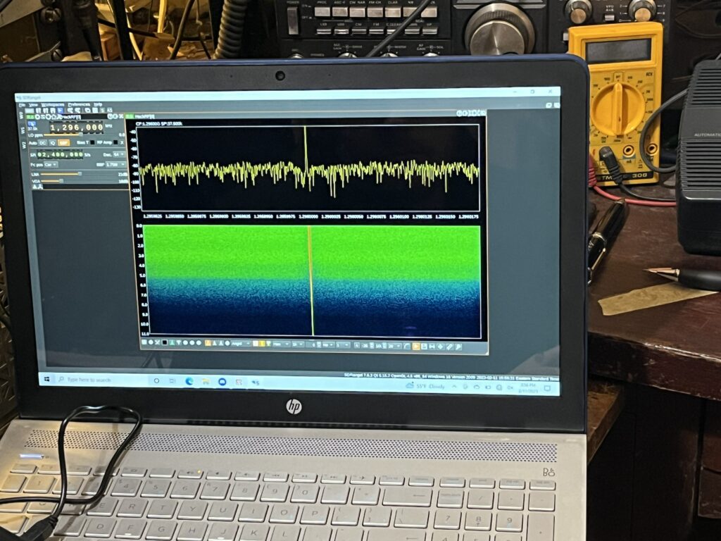

While exploring the SDR side of this project, we will need a device that is capable of transmitting and receiving the signals that are modulated/demodulated with the SDR software. Our SDR of choice for this project is the HackRF One. This device interfaces with our SDR software through a Micro SUB to USB 2.0 connector. We chose the HackRF One because of how much control we can have over our signal. It can operate on frequencies ranging from 1 MHz to 6 GHz, meaning that we can transmit directly on 1296 MHz without having to mix our signal. It has a variable bandwidth as well, being able to go as low as 375 Hz and all the way up to 500 kHz. This is valuable to us because we are able to change the bandwidth we are transmitting on easily allowing us to run a wider range of tests. In addition to this the HackRf One has SMA connectors for its antenna input/output, and for a clock reference input so we can connect our 10 MHz reference.

Figure 1: HackRF One
SDR Receiver (New Jersey): Since it would take too long to switch between transmit and receive mode on the HackRF during echo tests, we needed an additional SDR to use as a receiver. The requirements for this receiver were that it had to be capable of operating on 1296MHz, and that it had to be compatible with SDRAngel. We decided to use a SDRPlay, which was supported by SDRAngel. We had an SDRPlay RSP Model 1. This SDR allows for operation from 10KHz to 2GHz and allows for a bandwidth of up to 10MHz, so this SDR was qualified to work as our receiver.
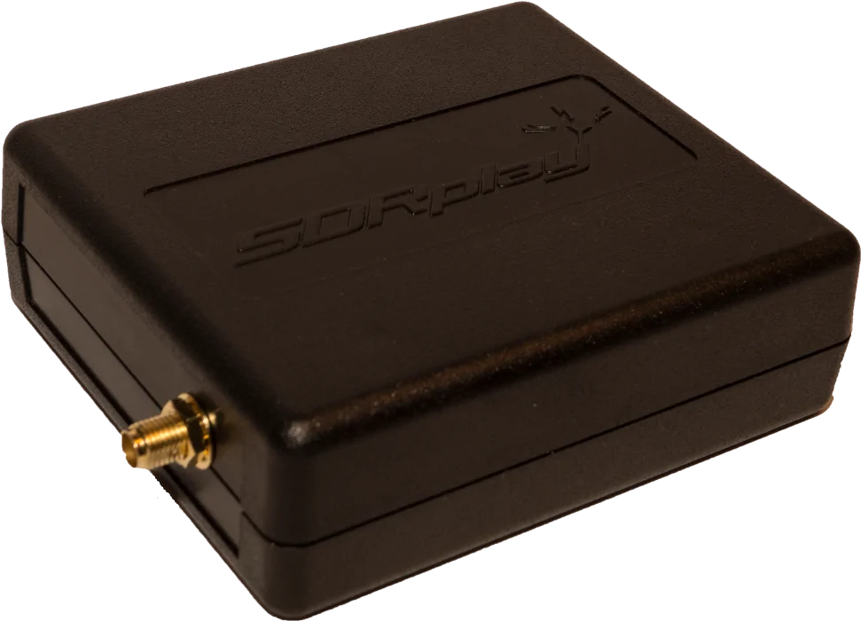
Figure 2: SDRPlay
SDR Receiver (Alaska): In order to get Mike set up to receive our transmission, we needed to send him an SDR that was capable of receiving on 10.7MHz and was also compatible with SDRAngel. We decided to go with RTL-SDR because it is a relatively inexpensive SDR that was capable of working with Mike’s ham set up and was also supported by SDRAngel. The RTL-SDR generally only goes down to 25MHz for receiving, but when using direct sampling mode with SDRAngel, we were able to get it to operate on 10.7MHz.
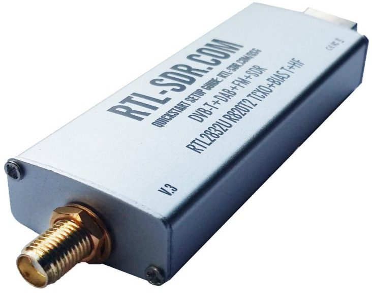
Figure 3: RTL-SDR