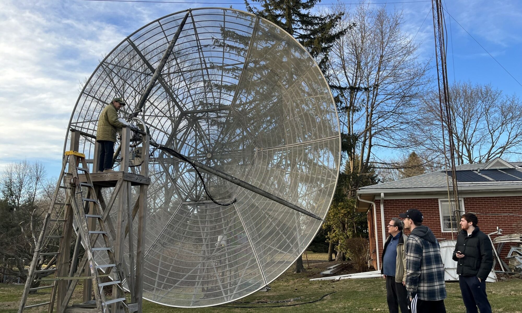

Moonbounce: This project uses EME propagation (also called Moonbounce) to bounce LoRa signals off the Moon. This form of communication uses the Moon as a passive reflector. Most MoonBounce communications are done at the 2 meter, 23 centimeter, or the 70 centimeter bands. Using Moonbounce comes with its challenges. The first major challenge is that the Moon is about 238,900 miles away, resulting in major path loss. Typically, when doing Moonbounce, and communicating in general, using the smallest bandwidth possible is desirable to obtain the highest signal to noise ratio (SNR). Having a high SNR will help mitigate the effects of the huge path loss. Another problem that must be taken into account is the Doppler Shift. Since the Moon and the Earth have a different relative radial velocity the frequency of the signal will be shifted. Doppler shift is a very important thing to consider when dealing with Moonbounce.
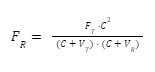
Doppler Shift: Doppler shift gets worse as you increase in frequency, so while we are operating on 1296 MHz it is important that we understand how the doppler shift will affect the signal during transmission, and how to compensate for it. At our frequency of 1296 MHz the doppler shift can be as much as 4 kHz. Depending on the exact reflection point on the lunar surface the shift in frequency can also vary. Since the Moon’s orbit around the Earth is not perfectly circular the relative velocity between the Earth and the Moon changes throughout the Moon’s orbit. To calculate the doppler shift between two different stations we must take into account the relative velocity between the Earth and the Moon at each location. Shown below in Equation 1 FR is the received frequency, FT is the transmit frequency, and C is the speed of light in m/s. VT and VR are the relative velocity between the Earth and the Moon at the transmitter and receiver respectively
LoRa: Our modulation technique, LoRa, is generally used for Internet of Things (IOT) applications. IOT refers to the interconnectivity and data exchange between devices/sensors. This technology is becoming increasingly practical in security systems, smart homes and cities, etc. Another impactful use that has been theorized is for use in emergency situations involving widespread blackouts due to infrastructure damage. IOT widely uses short range technologies such as Bluetooth, with long range requirements being solved using cellular communications . Cellular solutions provide the range, but use excessive energy. LoRa may provide a way for sending small chunks of data over long ranges when compared to WiFi or Bluetooth.
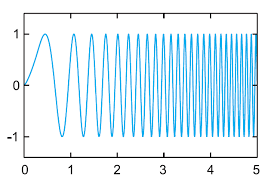
LoRa is one of a few low power wide area networks (LPWAN). These networks are characterized by low power, low cost, and long range. They are ideal for transmitting small amounts of data at longer ranges. LoRa uses a spread spectrum modulation scheme that is based on Chirp Spread Spectrum. Chirp Spread Spectrum modulation techniques work by deliberately spreading a signal in the frequency domain. The signals are made of a series of up-chirps and down-chirps, which essentially means that the signal increases (up-chirp) or decreases (down-chirp) in frequency in order to encode the message.An example of an up-chirp can be shown below in Figure 1. The x-axis in the graph is time, and the y-axis is the amplitude of the signal.
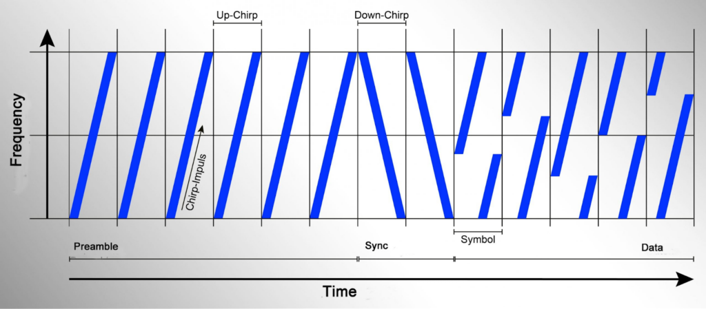
When demodulating a LoRa signal, it is much more common to see the signal expressed with frequency and time rather than with amplitude and time, like it is shown below in Figure 2. One thing to note about this graph is the fact that the message begins with a series of up-chirps, and is followed by 2 down-chirps. The up chirps are called a preamble, and the down chirps are called a synchronizing message. These are used together at the beginning of every LoRa modulated message to keep the receiver synchronized and indicate the beginning of a new message.
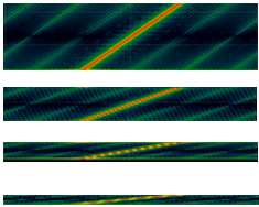
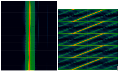
There are two aspects of LoRa that we can control, the bandwidth and the spreading factor. As mentioned in the Moonbounce section above, when dealing with Moonbounce a smaller bandwidth is preferred because it yields a higher SNR. LoRa follows this convention in that a lower bandwidth will allow for improved range because of its higher SNR, but it will also result in a lower bit rate. However, when going too low with bandwidth we can run into some problems. An extremely low bandwidth will result in a signal that is difficult to demodulate. Shown below in Figure 3 is a comparison of a LoRa signal with an extremely low bandwidth of 375 Hz, and a LoRa signal with a fairly normal bandwidth of around 10 kHz. In that comparison, it is pretty easy to see that when the bandwidth gets too low it can become difficult to determine the difference between an up-chirp and a down-chirp. It is important to keep this in mind when determining the bandwidth that we want to operate with. While an extremely low bandwidth like 375 Hz will look great when calculating our SNR, in practice we will have an extremely hard time demodulating that signal.
Another aspect of LoRa that we can control is the spreading factor (SF). Sometimes referred to as the sweep rate, the spreading factor essentially controls how much the data is spread in time. A comparison of different spreading factors can be seen below in Figure 4. The highest spreading factor that is available with LoRa is 12, and is shown as the first up-chirp in the screenshot. For our application, we will be using a spreading factor of 12 because a higher spreading factor allows for a higher reception sensitivity at the expense of a lower data rate