
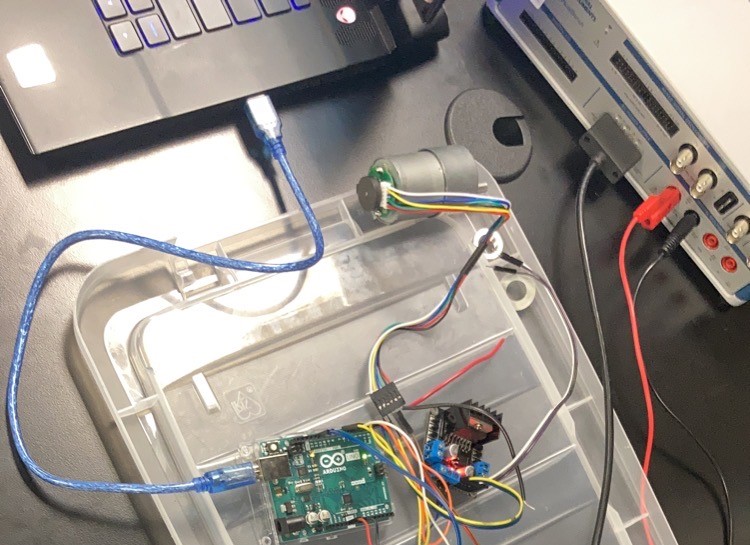
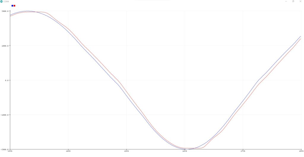
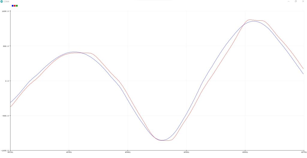
The group was able to implement a simple digital PID controller on the Arduino to precisely control the position of a motor with encoder. A function of time representing the desired motor encoder counts (blue) is inputted into the PID controller. The actual rotation of the motor in encoder counts (red) closely aligns with the desired position indicating that the the tuning parameters for the proportional, integral, and derivative terms are appropriate. In the two examples shown below, Kp = 2.0, Ki = 0.02, and Kd = 0.2.
For the rest of this specific post, I will be referring to motors with encoders as just motors. This does not necessarily apply for other posts.
The motors are being programmed on the Arduino which is a C++/C based language. In software, the motors were packaged in a Motor class to hold all the important parameters about a motor with encoder. The header file for the class is shown below. If you want a more detailed look at the code go here: https://github.com/bohrm1/Arduino-Motor-Control/tree/main/MotorEncoder_main .
class Motor
{
  private:
    int PWM;          //creating member variables to describe motor with encoder
    int In1;
    int In2;
    int ActualPos = 0;
    int Dir;

    int Kp = 0;       //constants for PID controller internal to class
    int Ki = 0;
    int Kd = 0;

    long prevT = 0;
    float eprev = 0;
    float eintegral = 0;

  public:
    Motor(void);
    void CreateMotor(int pwm, int in1, int in2);

    void SetMotor(int target, int kp, int ki, int kd);
    void Drive(int dir, int pwr);
    void SetPos(int pos);
    int GetPos(void);
};