Project Update 9: System Integration Progress and Computer Vision Updates

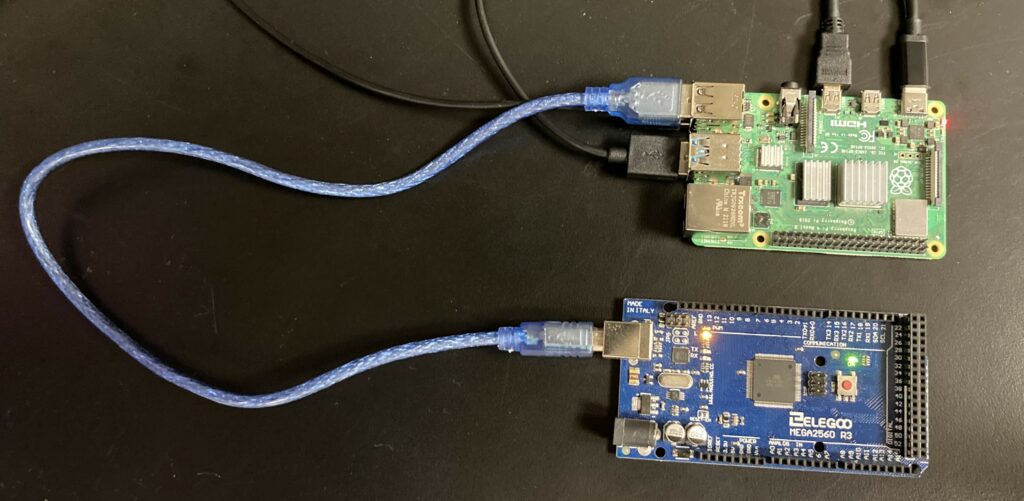
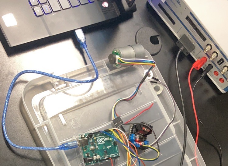
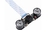
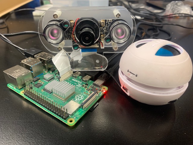
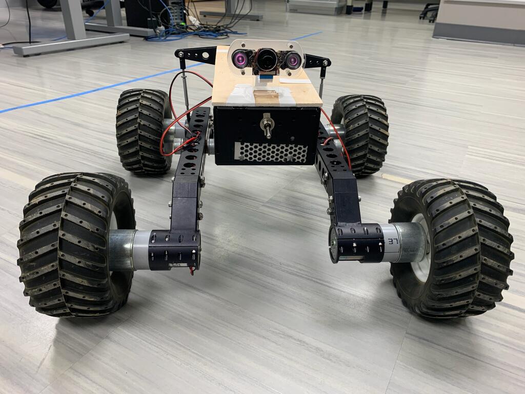
The team was able to successfully integrate the camera, motor, and audio subsystems with the rover drivetrain. A picture of the subsystems and initial integrated prototype are shown below.

Camera/Audio subsystem configured with Raspberry Pi
Fully Integrated Rover Prototype

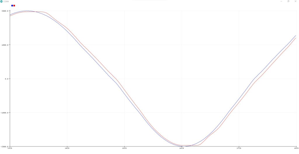
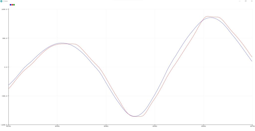
We were able to use VNC Viewer to establish a remote desktop connection with the Raspberry Pi wirelessly with an external laptop, in order to allow for improved interfacing capabilities. The preliminary testing results of the new-teleoperated control with that feature is shown below.

Computer Vision Updates

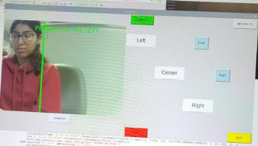
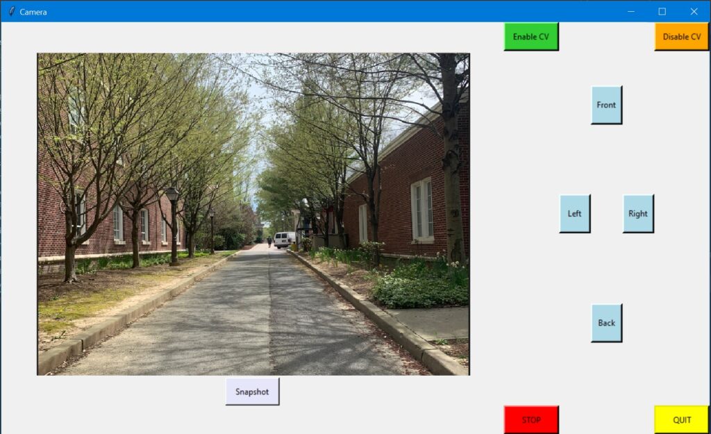
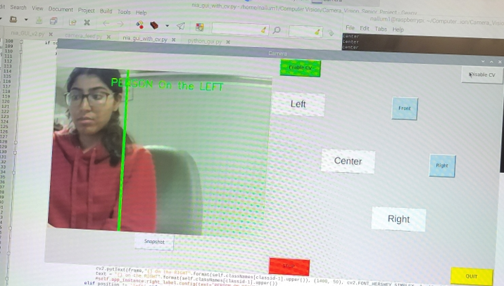
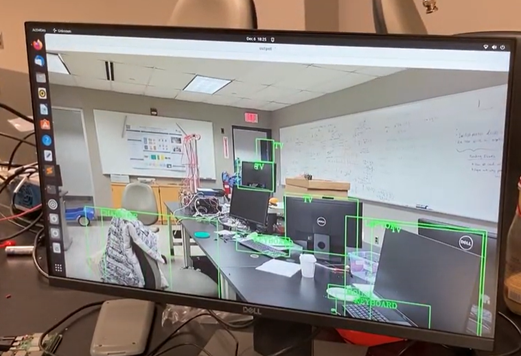
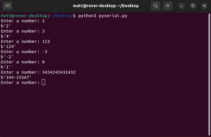
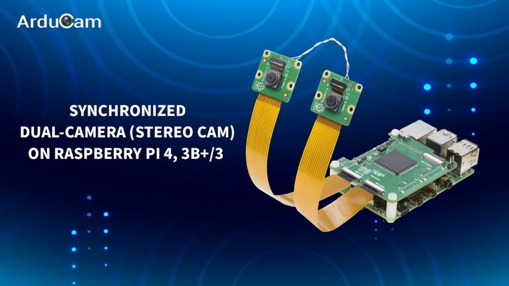
Integrating computer vision with an Arduino motor controller logic has proven successful through the use of the PySerial library. However, due to budget constraints, we were unable to obtain a stereo camera for improved accuracy in locating objects. Nevertheless, our team has focused on creating a remarkable semi-autonomous system, which is now operational. Our system features a single camera, but with the addition of computer vision integrated with a GUI, it provides users with valuable information regarding the location and distance of objects (this measurement is only shown in the termial). This extra guidance enhances the user’s experience and enables smoother operation of the device.

The image below show these features with the GUI interface.

Project Update 8: GUI Development and Computer Vision

We developed a GUI for the tele-operated rover functions using the Tkinter library in Python. This layout allows for more intuitive control of the motor for the basic steering capabilities, as well as with integrated camera access with a snapshot feature.

The “Snapshot” button allows for the user to capture an image of the current video feed and save it to the Desktop file path with the timestamp automatically saved in the filename.

We have intergated computer vision system with the GUI interface above, but limited to only detect humans for the sake of testing. However from eariler iteration it is able to identify many different indoor and outdoor objects. The image belows shows how the computer vision is able to tell you were the object is on the screen and draws a green line on the side the object is.

Project Update 7: Details on Motor Steering and Motor Rotating

The group created functions called DriveRover and RotateRover that could handle all of the processes and math that go into steering and rotating the rover. Essentially, they are functions used for multi-motor control. These functions accept four MotorNoEncoder objects to be passed in, one for each motor, and will generate the proper control and PWM signals for all four motors depending on the user input.

The diagram below shows the physical manifestations of the DriveRover function. Besides the motor objects that were instantiated from our MotorNoEncoder class, it also accepts a power and direction (dir) input to dictate both dictate the direction in which the motor will drive.

Below shows the basic functionality of both the DriveRover and RotateRover function.

Project Update 6: Fall Demo

The rover currently features a fully working tele-operated functionality through wireless keyboard control. The power supply issue was resolved by adding a separate source to power the Raspberry Pi, and the Pi can now also be connecting through serial communication on a shared WiFi network.

Below are two video demos highlighting the following:

  • Differential drive for all movement – unique steering algorithm controlled by tele-operated function
  • Smooth rotation using controlled speeds and direction, using modular and abstracted programming principles
  • Ease of use through simple user interface

Computer Vision Updates

Along with the rover demo we also showed the Computer Vision capabilities of classfication up to 80 different objects using the COCO dataset using the implenettaion of Yolo model. The image below is computer vision screenshot for our rover’s camera view with the object detection python code running on the raspberry pi.

The images below describes how the Yolo model works and what the COCO dataset is.

This image belows shows you how the overall system works as a block diagram.

Project Update 5: Python script running .wav file

The team was able to succesfully use the PyAudio python library in order to play a .wav file out loud. The reason this is important is because the group wants the rover to have some sort of feedback, whether that be auditory, visual, or preferably both. This python script enables the group to provide auditory feedback to persons in the vicinity of the rover. Here is a link to the PyAudio API documentation: https://people.csail.mit.edu/hubert/pyaudio/

Below shows the audio file called “test2.wav” as well as the python code used to play it out loud.

test2.wav

PyAudio Python code

#!usr/bin/env python  
#coding=utf-8  

import pyaudio  
import wave  

#define stream chunk   
chunk = 1024  

#open a wav format music  
f = wave.open("test2.wav","rb")  
#instantiate PyAudio  
p = pyaudio.PyAudio()  
#open stream  
stream = p.open(format = p.get_format_from_width(f.getsampwidth()),  
                channels = f.getnchannels(),  
                rate = f.getframerate(),  
                output = True)  
#read data  
data = f.readframes(chunk)  

#play stream  
while data:  
    stream.write(data)  
    data = f.readframes(chunk)  

#stop stream  
stream.stop_stream()  
stream.close()  

#close PyAudio  
p.terminate() 


Project Update 4: Raspberry Pi 4 to Arduino Mega Serial Communication

Figure 1: Raspberry Pi and Arduino Mega Serial Communication via USB

The group was able to send messages between the Raspberry Pi 4 and Arduino Mega via serial communication. A python script running on the Pi accepts a number from the command line and sends it to the Mega using a popular Python library for sending serial information called PySerial. The Mega then increments the number by 1 and sends it back to the Raspberry Pi which will display the new number to the terminal.

The serial.Serial(…) command on line 3 opens serial communication on port /dev/ttyACM0 because the Mega was connected to port /dev/ttyACM0 on the Pi. Notice how the baud rate on the Pi must match the baud rate on the Mega (115,200 Hz).

The terminal shows the result of running the Python code after uploading the Arduino .ino file to the Mega.

Python Code

import serial
import time
arduino = serial.Serial(port='/dev/ttyACM0', baudrate=115200, timeout=.1)
def write_read(x):
    arduino.write(bytes(x, 'utf-8'))
    time.sleep(0.05)
    data = arduino.readline()
    return data
while True:
    num = input("Enter a number: ") # Taking input from user
    value = write_read(num)
    print(value) # printing the value

Arduino Code

int x;

void setup() {
  Serial.begin(115200);
  Serial.setTimeout(1);
}

void loop() {
  while (!Serial.available());
  x = Serial.readString().toInt();
  Serial.print(x + 1);
}

Running PySerial in Raspberry Pi Terminal

Project Update 3: Simple PID Controller

Figure 1: Motor with Encoder

The group was able to implement a simple digital PID controller on the Arduino to precisely control the position of a motor with encoder. A function of time representing the desired motor encoder counts (blue) is inputted into the PID controller. The actual rotation of the motor in encoder counts (red) closely aligns with the desired position indicating that the the tuning parameters for the proportional, integral, and derivative terms are appropriate. In the two examples shown below, Kp = 2.0, Ki = 0.02, and Kd = 0.2.

Figure 2: PID Test 1-Simple Sine Wave
Figure 3: PID Test 2-Two Sine Waves Overlapped

For the rest of this specific post, I will be referring to motors with encoders as just motors. This does not necessarily apply for other posts.

The motors are being programmed on the Arduino which is a C++/C based language. In software, the motors were packaged in a Motor class to hold all the important parameters about a motor with encoder. The header file for the class is shown below. If you want a more detailed look at the code go here: https://github.com/bohrm1/Arduino-Motor-Control/tree/main/MotorEncoder_main .

class Motor 
{
  private:
    int PWM;          //creating member variables to describe motor with encoder
    int In1;
    int In2;
    int ActualPos = 0; 
    int Dir;

    int Kp = 0;       //constants for PID controller internal to class
    int Ki = 0;
    int Kd = 0;

    long prevT = 0;
    float eprev = 0;
    float eintegral = 0;
    
  public:
    Motor(void);
    void CreateMotor(int pwm, int in1, int in2);

    void SetMotor(int target, int kp, int ki, int kd);
    void Drive(int dir, int pwr);
    void SetPos(int pos);
    int GetPos(void);
};

Project Update 2: Hardware Schematics Version 1

Three schematics were developed, a schematic for the onboard robot, for the onboard power station, and for the Raspberry Pi 4 workstation. Two schematics were developed for the onboard robot–one for a robot with 2 motors with encoders and another with 4 motors without encoders. This is because the group has not finalized the mechanical design of the chassis yet.

Besides the motors, other important components include the servos which we intend on using to create an automatically open enclosure for medical supplies, cameras to be used for the raspberry pi, and temperature and humidity sensors. We intend on using an Arduino Mega for motor and sensor control.

Project Update 1: Basic Motor Test and Camera for Rover

This week our team was able to add the DC motors (without encoders) back onto the metal chassis frame. The original wires of the motors needed to be lengthened and tied together, which we were able to accomplish by soldering them to wires within conduits and using electrical tape to cover the junctions.

We were able to set up the Arduino-motor circuit from within the base frame, and used a simple code script to test the motion of the motors with the wheels on the prototype. The video below shows how the wheels and motors were able to spin in both directions, and at differing speeds when designated.

Rover Camera

As we were testing out the rover motors we were looking at camera options to buy. Although we want a stereo camera that works with the raspbery pi. at the moment it might be a bit out a budget to we are planning to look further into the single camera options with some infrared sensors to help with night time object detection.

Stereo Camera Option

Single Camera Option (with infrared sensors)