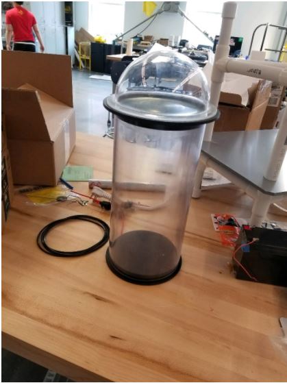

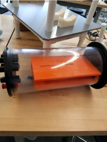
The team designed a multi-level tray system to hold all of the on-board electronics including our micro-controller, buck converter, bus bars, motor drivers, and IMU sensor. The image above shows the final 3D-printed design fitted snugly in the enclosure. Soon all our electronics will populate the tube.
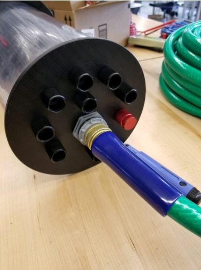
Here is an image of the end cap located on the enclosure tube. There are a total of 8 holes fitted with penetrators purchased from BlueRobotics. Six of the holes will have the thruster cables fed through to the motor drivers. The remaining two holes will house the power cables from the LED lights, and camera and additionally the coaxial cable. The main tether is fed through a water-tight flange that feeds the main power lines, Ethernet, and video cable between the onshore station and on-board electronics. The red plug is a nifty tool that attaches to the end cap and allows the release of pressure within the tube simply by rotating its back cap.
Here is a video that demonstrates a thruster test designed using a pulley system to measure current draw and weight difference which the team could then use to calculate thrust values. The test was developed to provide the team with adequate data to determine if the bilge pump we had purchased would provide the necessary thrust to maneuver the ROV.