Design Process
In the early phases of the design process, it was originally thought that the device would be more similar to a neck pillow that would only move the user’s head. After realizing the issues associated with this idea, the device was turned into a more full body device that will cover the upper portion of the body. This will allow for the device to focus more particularly on positional sleep apnea that is associated with the position the individual is in. From there, research was done in order to determine the positions in which apnea episodes are minimized most significantly for Positional Sleep Apnea patients. It was determined that patients on either their left side, right side, or in an elevated position experience less apnea events. Once these three positions were determined, three overall design ideas were presented. The three design ideas varied in the number of air pockets that would be used to move the patient as well as the overall shape of the sleeping device.
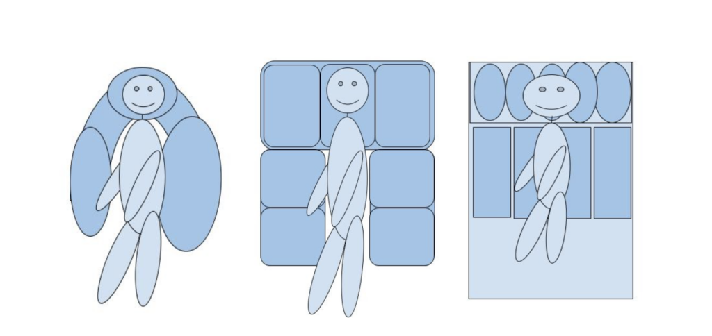
The figure above shows the three design options that were considered before deciding on a final design. Each design option contains a different amount of air pockets that would be utilized to move the patient. For the left image, the 3 air pocket design, the cost would be the least, for it would require the least amount of material, however, it would not have good control in moving the user due to the small amount of air pockets. For the right image, the 9 air pocket design, this would be the most costly from needing to use the most material, but it would have the most control over the user due to the many air pockets. The middle image, the seven air pocket design, will give us the ability to control the movement of the user, while also allowing for the user to be comfortable while they are sleeping, ensure the safety of the user, and provide a durable device, which is why this was chosen as the final design.
Final Design
After consideration of the requirements and specifications of the device, the design idea with seven air pockets offered the most optimal design. This design offered the ability to control the movement of the user, but still allowed for the user to be comfortable. The device will move the user into one of the three positions. By utilizing pressure sensors, it can be determined what position the user is in and move them into a different position. The three positions are elevated or upright, onto the user’s left side, and onto the user’s right side. These three positions have been shown to be the optimal positions for individuals with positional sleep apnea as opposed to sleeping on one’s back. Since each user has a unique anatomy, certain positions are better suited for some users than others. Therefore, moving the patient into one of these three positions, while continuing to monitor the oxygen saturation can allow for the device to react accordingly and move the user into a different position if one is not alleviating the apnea symptoms. To move the user on their left side, the three air pockets along the right will be fully inflated and the middle pocket along the top of the device will be inflated slightly. To move the user onto their right side, the three air pockets along the left will be fully inflated and the middle pocket along the top of the device will be slightly inflated. To move the patient into an upright or elevated position, the three top air pockets will be fully inflated with the middle left and right side air pockets slightly inflated. This will aim to move the user into the new position in a way that will not wake them up. The figure below shows the SolidWorks model for the final design solution.

Construction Process
Pneumatic/Mechanical Component
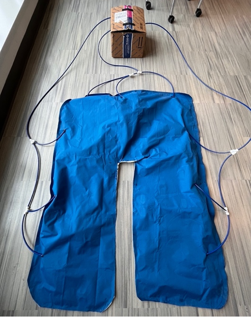
The pneumatic component of the device is comprised of seven air pockets made of out PVC free material (similar to that of air mattress). Utilizing air pumps, these air pockets can be inflated and deflated in order to move a user into one of the three desired positions, each of which is geared towards reducing the number of apnea events. The air pumps used for this device functioned at a noise level that would disrupt one’s sleep normally, so a muffling apparatus was created in order to insulate the air pumps and minimize the noise produced while function.
Electrical Component
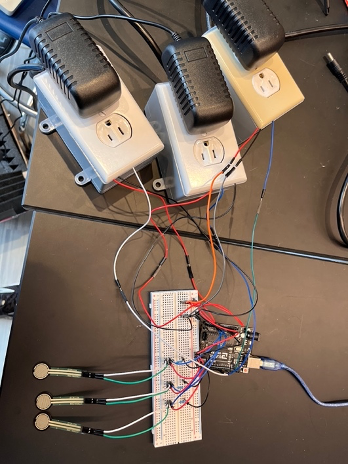
The electrical component of the device contains an Arduino Uno, three relays, a pulse oxygen sensor three pressure sensors, 3 powered outlets, and an extension cord. The Arduino powered outlets allow for the air pumps to be plugged in, with a relay controlling the current supplied to them. Therefore, the Arduino code can turn the relays on and off, in turn turning the air pumps on and off. The pressure sensors and pulse oxygen sensor measure values that are inputs within the Arduino code. When these measurements reach a threshold value, it prompts the air pumps to turn on and inflate the device, changing the user’s sleeping position.
Overall Constructed Design Description
To put together the overall device, epoxy was used to seal the edges. Epoxy was decided to be used rather than sewing as it could create an airtight seal that would not allow air to leak out of the seam. The device will inflate into three different positions. To accomplish this, an air pump was allocated to each of the three positions. Tubing was put into each of the air pockets. To move the user onto their left side, the three right air pockets had tubing placed into them along the side. These three tubes were connected, and one overarching tube was placed into the specific air pump. This was done so that with the turning on of this air pump, all three desired air pockets would be inflated. A similar process was repeated to move the user into the right position and the elevated position. The two upper corner air pockets had two separate sets of tubing that fed into them, one designated for the upright position and one for their respective sides. The tubing was sealed with epoxy to minimize the risk of leaks.
To inflate and deflate the device, the air pumps were set to turn on and off depending on the desired position. The air pumps operate at a loud noise level, so a box was created to muffle this sound. This box is lined with foam, soundproof insulation to absorb the noise of the air pumps. This foam is heat resistant and the tubing was fed out of the box to allow for proper ventilation and airflow into the pumps to allow them to function properly and not overheat.
The sensor components dealt with constructing the pulse oxygen sensor and the pressure sensors to ensure that they would allow us to obtain the data we needed. There were three pressure sensors utilized in the design, one on the right side, one on the left side, and one on the top portion of the device. Both in connection with the Arduino Uno used, blood oxygen saturation levels as well as pressure values were obtained and ready to be utilized as inputs for the overall electrical component of the device.
The electrical component consists of the Arduino, three pressure sensors, a pulse oxygen sensor and three relays. Three 5V relays were used as on and off switches for the air pumps. The Arduino code contains multiple if statements, where if the blood oxygen saturation level reaches the threshold of 93%, in addition to the pressure sensor detecting a value above 200 mV, the air pump corresponding to the specific pressure sensor will turn on, rotating the user’s position. The value of 200 mV was chosen for the test code; however, this value would be higher when an individual’s body weight is placed on the sensor. The need for a power supply that would supply enough power to the device and allow it to plug into the wall prompted the construction of an Arduino controlled power outlet. This allowed for the air pumps to be controlled by the sensor values. The power-controlled outlet contains an electrical outlet box, an electrical outlet, and electrical outlet box cover plate, as well as a power strip that allows the outlet to be plugged into the wall. The power strip was cut, so only the wire with the plug was utilized. The wire was then stripped with three wires inside of it. These three wires, as well as the relay, were electrically connected to the electrical outlet, which was then placed within the electrical outlet box, along with the relay. The electrical outlet box and electrical outlet box cover plate allowed for electrical safety when testing the device. Since this device contains three controlled power outlets for each air pump, an extension cord was also utilized to easily plug in all three power strips cords into the wall at once. Each relay within each outlet is connected to the Arduino, allowing it to be controlled by the Arduino code. The air pumps are then plugged into the power-controlled outlets, allowing the relays to turn them on and off through switching the current to the power outlet on and off.
Design Figures