Mid-Semester Progress Report

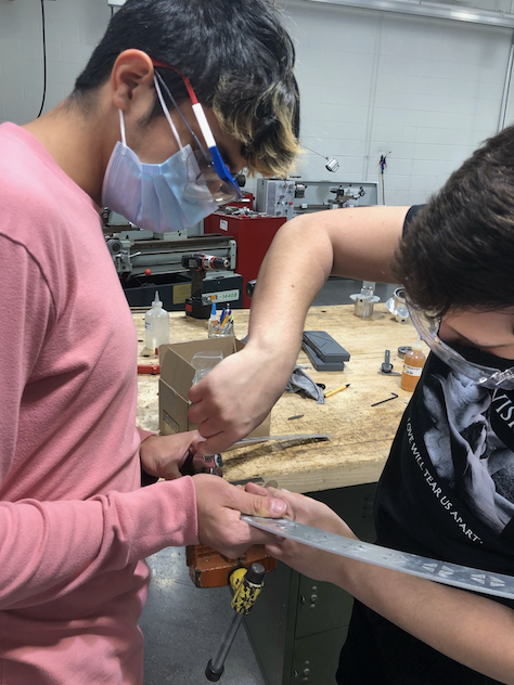
At this point in the semester we have completed the full construction of our gimbal rig. We are entering the testing phase for our drone very shortly. We will be testing both on and off the gimbal rig in the coming weeks. Things we will be testing for include battery life during flight, stabilization, and autonomous movement. We will also be implementing our camera component once stabilization testing is complete to start taking and storing photographs with the drone.

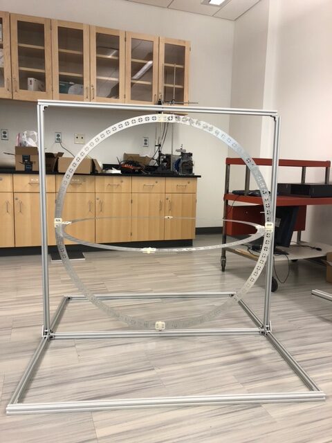
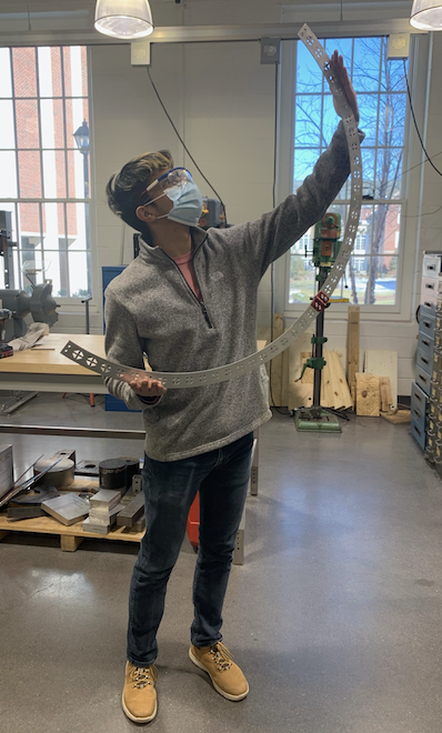
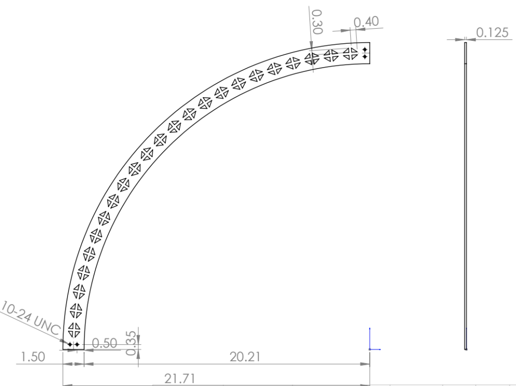
Here, we have the gimbal rig full assembled. All there is left to do is to attached the drone and begin testing! This gimbal rig is located on the 2nd floor of the STEM building, inside the drone lab.

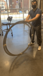
Here, we have a demonstration by William showing the gimbal rig rotating with ease. This will allow students to test for degrees of freedom whenever we are incorporating tuning values.

Assembly of the Rings

As components of the gimbal rig were being manufactured in the Machine Shop, students were simultaneously assembling the rings to get a visualization of the final product. Students worked diligently in order to have a gimbal rig ready for continuous testing of the manual and autonomous features in the drone.

Here, we have William and Fabian attached the aluminum rings to the 3D printed sleeve bearing. Previously, the holes on the sleeve bearings were also tapped in order to have the screw go through.

Here, we have Fabian posing with a half assembled ring after connecting the sleeve bearings to the two yaw rings.

Construction of the Yaw Ring

Team got to work in the machine shop following the winter break. One of the objectives of the APD group was to create a gimbal testing rig. This will allow the group to operate the drone safely, save money from breaking components during testing, and can be utilized for future drone projects after this semester.

Here, we have a snapshot of the yaw ring that was sent to TCNJ Machinist for review. Shortly after the approval, the 8020 aluminum that the group purchased was then utilized under the water jet.

Here, William is using a tap to thread holes through the newly cut yaw rings. The threaded holes will help connect all the components inside the bearing housing.

Modeling Control System via Simulink

As the APD group work towards debugging and implementing a new control system in the Navio2 and Raspberry Pi 4, students began constructing and simulating the control system of the drone via MATLAB Simulink. The objective was to model the behavior of the drone in various scenarios. By doing, it will help students understand what specific values the PIDs within the drone are required in order for it to fly manually, and then autonomously.

Here, we have a snapshot of the overall control system of the drone. It includes default values for the roll, pitch, yaw and altitude values. All values are then fed into the summing junction, where the system will begin to calculate the error between what is desired versus what was calculated.

Here, we have a snapshot of the altitude control of the APD successfully implemented via MATLAB Simulink. The values derived from this model will eventually be utilized in the actual coding of the drone when operating manually and autonomously.

Motor Thrust Testing

In order to determine the thrust generated by our motors to lift the drone, an apparatus attached to a load cell was used. This apparatus is pictured below.

A mount according to the manufacturer’s specifications for our motor (iFlight XING 2814 880KV) was developed to be used on the thrust measurement apparatus. The tapped holes used for connecting the motor to the mount were M3x0.5 sized holes as specified by the manufacturer and as indicated by the diagram below.

Upon completion of the motor mount, the thrust measurements could be completed. These were done by use of a flight controller and a 22.2 volt LiPo battery. Thrusts in pounds for each motor are shown in the table below. Note that values colored red were conducted at throttles that began to cause damage to the motor, the quadcopter will not typically operate at such levels.

22.2 v batteryThrust (Pounds)
ThrottleMotor 1Motor 2Motor 3Motor 4
33%0.811.631.541.49
50%2.822.822.732.73
67%4.144.13.923.92
75%4.84.84.1Not Tested

These thrust measurements are suitable for lifting the drone as the total thrust will be equal to about ~16 lb during upward throttle.

Welcome to the APD!

The Goal

The APD(Autonomous Photography Drone) plans to be an autonomous quadcopter capable of navigating to a real-estate property given and address and taking photographs while circling the property.

Who are we

The team consists of four engineers from three different disciplines:

  • Evan Hope is a computer engineer developing the automation, computer vision, and application features of the project.
  • William Apostolico is a mechanical engineer responsible for creating the testing mechanism for the drone and performing structural analysis on the drone body.
  • Fabian Mestanza is an electrical engineer focused on control theory and ensuring the drone can perform stable flight.
  • Alex Bolen is an electrical engineer focused on the power system of the drone, as well as contributing to the development of the drones control system code.
Advisors
  • Ambrose Adegbege is an associate professor for the department of electrical and computer engineering at TCNJ. Dr. Adegbege research interests include: constrained control, robust control, antiwindup design, and control optimization.
  • Mohammed Alabsi is an assistant professor for the department of mechanical engineering at TCNJ. Dr. Alabsi research intrests include: machine learning, adaptive and fault tolerant control, smart manufacturing, machine health monitoring, mechatronics.

Stay tuned for more posts about the challenges we face and solutions we find during development of the APD!