Assembly of the Rings

As components of the gimbal rig were being manufactured in the Machine Shop, students were simultaneously assembling the rings to get a visualization of the final product. Students worked diligently in order to have a gimbal rig ready for continuous testing of the manual and autonomous features in the drone.

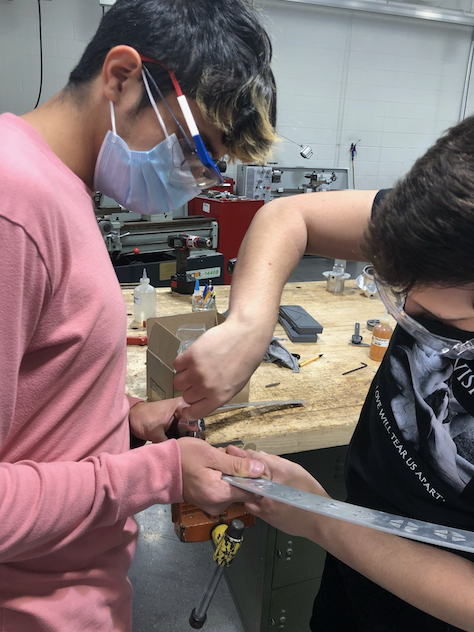
Here, we have William and Fabian attached the aluminum rings to the 3D printed sleeve bearing. Previously, the holes on the sleeve bearings were also tapped in order to have the screw go through.

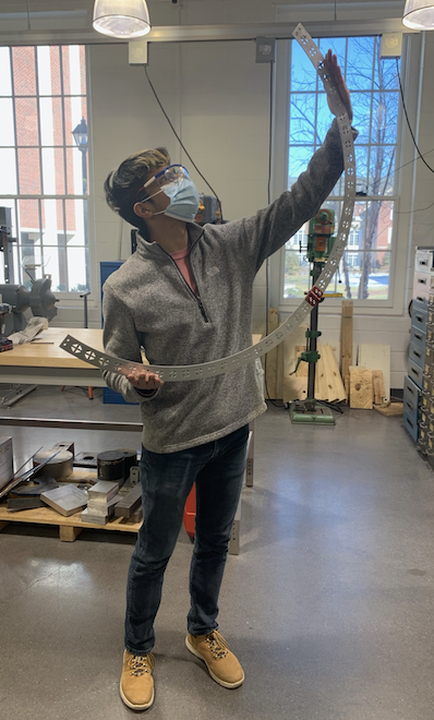
Here, we have Fabian posing with a half assembled ring after connecting the sleeve bearings to the two yaw rings.

Construction of the Yaw Ring

Team got to work in the machine shop following the winter break. One of the objectives of the APD group was to create a gimbal testing rig. This will allow the group to operate the drone safely, save money from breaking components during testing, and can be utilized for future drone projects after this semester.

Here, we have a snapshot of the yaw ring that was sent to TCNJ Machinist for review. Shortly after the approval, the 8020 aluminum that the group purchased was then utilized under the water jet.

Here, William is using a tap to thread holes through the newly cut yaw rings. The threaded holes will help connect all the components inside the bearing housing.

Modeling Control System via Simulink

As the APD group work towards debugging and implementing a new control system in the Navio2 and Raspberry Pi 4, students began constructing and simulating the control system of the drone via MATLAB Simulink. The objective was to model the behavior of the drone in various scenarios. By doing, it will help students understand what specific values the PIDs within the drone are required in order for it to fly manually, and then autonomously.

Here, we have a snapshot of the overall control system of the drone. It includes default values for the roll, pitch, yaw and altitude values. All values are then fed into the summing junction, where the system will begin to calculate the error between what is desired versus what was calculated.

Here, we have a snapshot of the altitude control of the APD successfully implemented via MATLAB Simulink. The values derived from this model will eventually be utilized in the actual coding of the drone when operating manually and autonomously.