
In order to begin the design of the vehicle, specific goals and criteria need to be established. It was decided that the vehicle’s range of operation is to be limited to flat, indoor spaces, such as hallways and classrooms. It was important for the top speed to be faster than the average person walks. The reason is so the vehicle can maintain walking speed without operating at maximum output. The most important criteria are that it can suitably carry and be operated by a Nao robot.
These requirements were enough to establish the size and speed, as well as other aspects of the vehicle. The robot is over 22 inches, and back to front is nearly 11.5 inches with its arms extended forward, Figure 2 depicts these measurements. A vehicle 3 feet long and 2 feet wide was determined to be a reasonable size to house the robot as well as have plenty of extra room for other necessary components. Given a vehicle of this scale, 8-inch wheels were selected. The operating environment of the vehicle eliminated the need for a suspension system, as the floor indoors is smooth. Lastly, it was determined that the average walking speed of a person is around 3 mph a top speed of 4.5 mph was established. At this point the general specifications have been layed out. It is known only that a 3×2 ft vehicle, with 8 inch wheels, must travel at a top speed of 4.5 mph. In order to achieve this, the design must become more detailed. A more thorough description of the design will be broken down into three sections: body components, steering and drivetrain.
The body of the vehicle will be comprised centrally around an eight inch thick, 3×2 ft. aluminum 6061. Having a base plate allows flexibility in the layout and spacing of the components and the placement of the Nao robot. Everything will be mounted on to the plate. Alterations need to be made to the plate before it can be used. A section measuring 6.5’’ by 12’’ in the each of front corners must be removed. This size was determined to be necessary to allow room for the front tires to turn without hitting the body. The details of this calculation will be addressed in the steering design, Section 2.4. Similarly; the rear corner sections need to be removed to allow space for rear tires. However, since the rear tires will not be turning, the section that must be removed is only 3’’x 9’’. The tire is 1.75’’ thick, with an 8’’ diameter. The tires will all be within the profile of 3’x2’, meaning that they will not be sticking outside the plate.
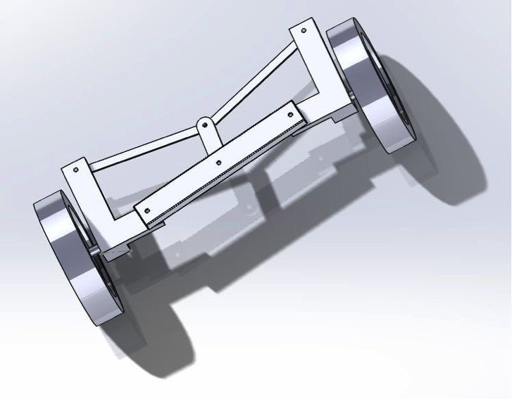
It was important to keep the appearance and functionality of the vehicle as close as possible to the way a typical car works. A humanoid robot will be operating this vehicle so it was determined that the interaction between operator and vehicle should be similar to the way a human operates a vehicle. This dictated that the vehicle would be front wheel steering. The steering system will utilize a main axle, made from the support skeleton for the base plate, tie rods, and a central tie rod-connecting piece. The wheel’s axle will be attached to a lever arm, also known as a steering knuckle.
The vehicle is to be powered by a rear wheel axle drive train. The drive train will be comprised of a motor, interfaced with a gearbox, a chain and two sprockets.
