
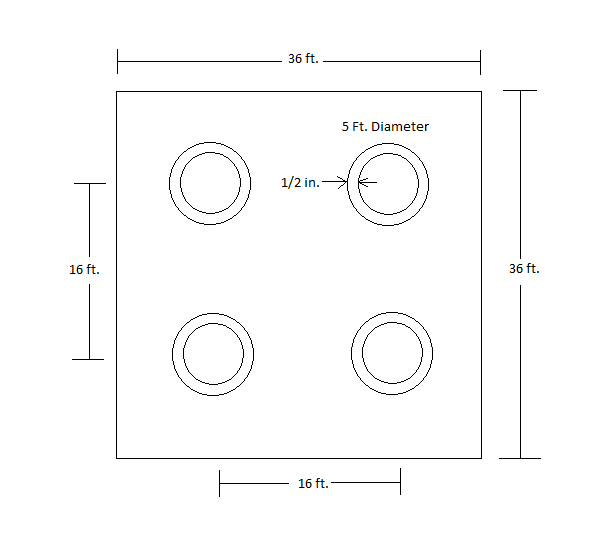
The team has completed the final design for the size and configuration of the drilled shafts that will be used for all three piers. The following plan shows the dimensions and locations of the four 5 ft. diameter drilled shafts. They will also contain a 1/2″ thick permanent steel casing and be embedded 110 ft. into the soil. 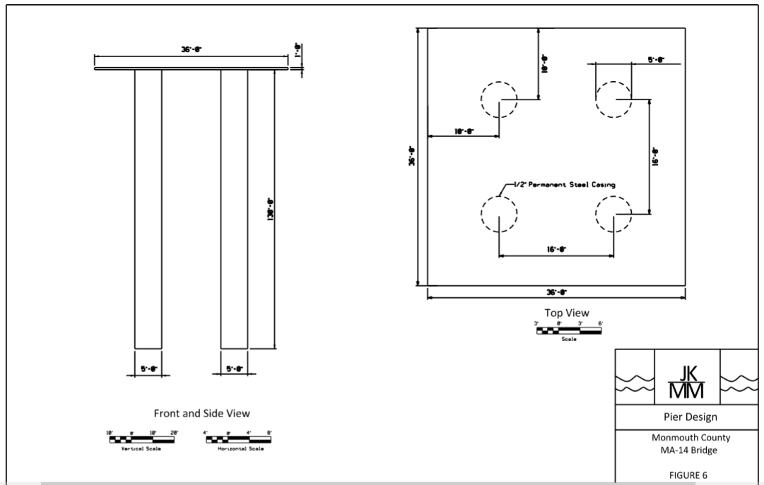
All posts by Jessica Ansley
Deep Foundation Design Update
Prestressed concrete piles were originally proposed for the deep foundation design. Once design began it was determined that it would require multiple piles with large diameters in order to reduce the lateral deflection to an acceptable amount. Driving these large piles in such close proximity to the required depths was not feasible, therefore concrete drilled shafts with permanent steel casing were selected for the deep foundation design instead. For the deep foundation design at both the piers and abutments, four 5 feet diameter drilled shafts were selected. While the diameter is 5 feet in total, the drilled shafts have ½” thick steel permanent casing around the concrete. Making the diameter of the concrete 49 inches with a compressive strength of 6000 psi. The total length of the drilled shaft for the piers is 130 feet, with an embedment depth of 110 feet. For the abutments the total length of the drilled shafts are 110 feet embedded fully into the soil without any stick height. The following diagram displays the drilled shaft configuration for both the piers and abutments.
Pile Design
Using the software APile, the team was able to select piles for the abutments and piers based off of the required axial capacity. A group of four 36 inch diameter piles will be used for both the abutments as well as the piers. An embedment depth of 88 feet is required at the piers while a depth of 101 feet is required for the abutments, putting the piles into the dense sand stratum for both locations. Next the lateral deflection of the piles was determined using the software Group. Five separate load cases were analyzed for the pile group at the abutments and the piers. The lateral deflection at the abutments was under 1 inch for all five load case scenarios. However, the deflection at the piers exceed the maximum allowable deflection. Therefore, the team will need to consider other options for the abutment design.
Soil Profile
The geotechnical team has finalized the soil profile. The ground water table, existing and proposed grades lines, as well as the bridge limits are now included as well.
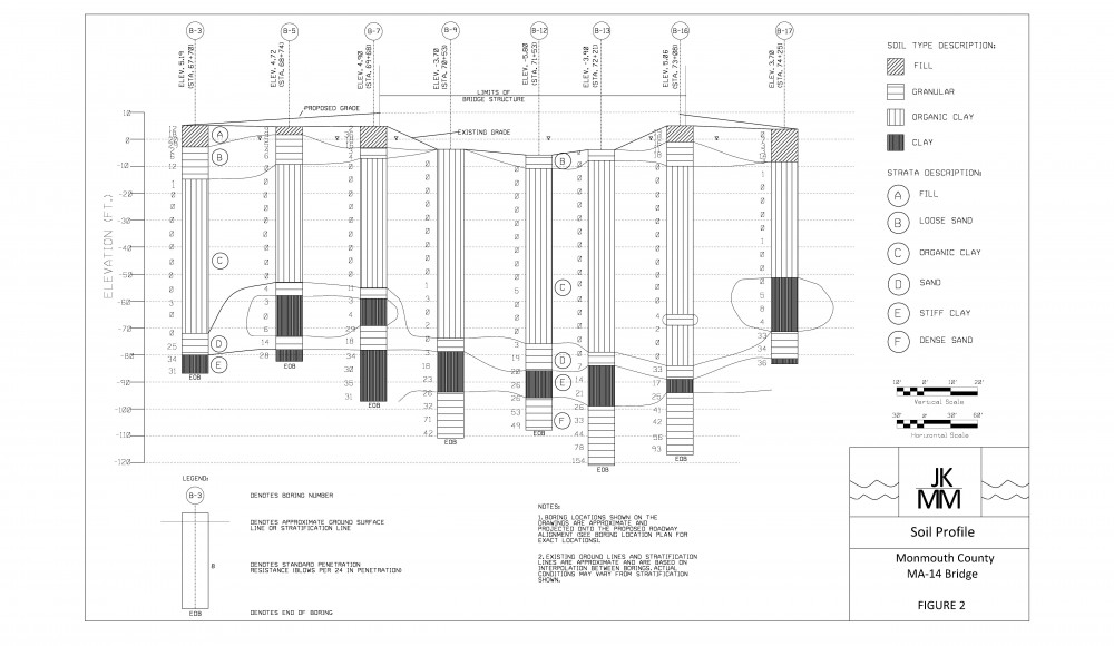
Site Plan
The team developed a site plan which includes the locations of the boring logs used for the soil profile. A conservative design approach was used while selecting which borings to use for the profile. Of the sixteen boring logs available, eight were located on the westbound side while the other eight were directly across on the eastbound side. The eight that were chosen for each location along the bridge contain the poorest soil conditions.
