Category Archives: Updates

Approach Embankment

Figure 4a Approach Embankment Figure 4b Approach Embankment

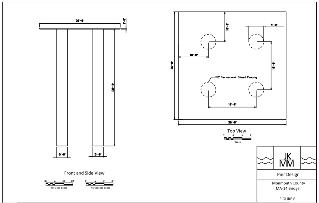
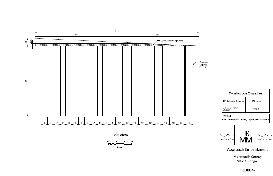
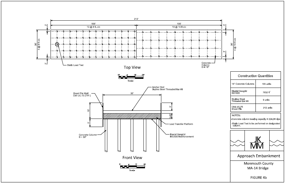
A column supported embankment design method was selected for the approach embankment design.  In this design, 18″ diameter concrete columns will be spaced 8 feet center-to-center for the first 106 feet (starting at the bridge abutment).  After the first 106 feet, the spacing of the concrete columns increases to 10 feet center-to-center until the end of the approach.  The load transfer platform used in this design will be 3.25 ft thick.  The load transfer platform is used to distribute the load of the embankment to the columns below.  Additionally, Tensar Biaxial Geogrid BX1500 was selected as a reinforcement layer between the load transfer platform and the top of the concrete columns.  This reinforcement is necessary to prevent the columns from punching through the fill of the embankment.  Each approach embankment will require 105 18″ concrete columns and 7632 sq. feet of geogrid reinforcement.

Pier Design

The team has completed the final design for the size and configuration of the drilled shafts that will be used for all three piers. The following plan shows the dimensions and locations of the four 5 ft. diameter drilled shafts. They will also contain a 1/2″ thick permanent steel casing and be embedded 110 ft. into the soil. Untitled

Deep Foundation Design Update

Prestressed concrete piles were originally proposed for the deep foundation design. Once design began it was determined that it would require multiple piles with large diameters in order to reduce the lateral deflection to an acceptable amount. Driving these large piles in such close proximity to the required depths was not feasible, therefore concrete drilled shafts with permanent steel casing were selected for the deep foundation design instead. For the deep foundation design at both the piers and abutments, four 5 feet diameter drilled shafts were selected. While the diameter is 5 feet in total, the drilled shafts have ½” thick steel permanent casing around the concrete. Making the diameter of the concrete 49 inches with a compressive strength of 6000 psi. The total length of the drilled shaft for the piers is 130 feet, with an embedment depth of 110 feet. For the abutments the total length of the drilled shafts are 110 feet embedded fully into the soil without any stick height. The following diagram displays the drilled shaft configuration for both the piers and abutments.

 Untitled


Bridge Shape

With the inputs finished into HEC-RAS, the minimum height of 12′ above high tide was kept.  The mean sea level is 0′, plus the high tide at 7′.  This puts the low chord of the bridge at 19′.  Even though the current model shows a pile design, the pile design is not complete.  Once a pile design is selected it can be inputted into HEC-RAS and the scour can be ran on the model.


Brige shape with old piles

Bridge Abutment

Scan0002

With an embankment height of 10 feet, the bridge abutment dimensions were determined as indicated on the drawing provided. Because the abutment is supported by piles, the bearing capacity was not determined for the soil directly beneath the abutment. The wall was checked for sliding and overturning. For sliding, the resistance force was calculated to be approximately 5,000 lb/ft with a driving force of 3,500 lb/ft. The abutment was resistant to sliding along the base. For overturning, the resistance moment was calculated to be 31,000 lb*ft/ft and the overturning moment was 13,500 lb*ft/ft. The abutment was safe from overturning.

Pile Design

Using the software APile, the team was able to select piles for the abutments and piers based off of the required axial capacity. A group of four 36 inch diameter piles will be used for both the abutments as well as the piers. An embedment depth of 88 feet is required at the piers while a depth of 101 feet is required for the abutments, putting the piles into the dense sand stratum for both locations. Next the lateral deflection of the piles was determined using the software Group. Five separate load cases were analyzed for the pile group at the abutments and the piers. The lateral deflection at the abutments was under 1 inch for all five load case scenarios. However, the deflection at the piers exceed the maximum allowable deflection. Therefore, the team will need to consider other options for the abutment design.

Embankment Primary Settlement

Using the EMBANK software the team was able to analyze the settlement of the soil profile under the approach embankments.  The soil strata used for this software was selected from the soil profile created using the boring logs, more specifically Boring B-16.  The software tested five separate scenarios in order to find the maximum settlement, which included creating sub layers for the strata of organic clay.  The maximum settlement was calculated to be 32.59 inches, or 2.72 feet, when the organic clay layer was split into four sub layers.  These calculations reinforce that soil remediation is a crucial element of this design.

Senior Project I Presentation


IMG_9910

On December 2, 2015 the team gave a successful presentation of the progress made on the Monmouth County Bridge MA-14 Geotechnical and Hydrological Design during Senior Project I.  The presentation included an overview of the site visit made in August, the realistic and design constraints, alternative designs, final design selection, and overview of our engineering cost and budget. Next semester, the design phase of this project will begin in Senior Project II.


Watershed Properties and Flow

The last of the watershed properties were found.  The average slope was found to be 5.26% and the longest hydraulic length was found to be 30,750 feet.  These two were found using four topographic maps.  Using the SCS time of lag, the time of lag was calculated to be 2.422 hours.  With all of the watershed properties the peak flow was found using HEC-HMS.  The flow was found to be 3,157 cfs.  This was done using a c value of 150.

Alternative Design

After considering the realistic and design constraints, alternative design options were considered for the soil remediation, embankment design, abutment design, and foundation design of the Monmouth County MA-14 Bridge. For the soil remediation, both preloading and wick drains were considered as a method to accelerate the consolidation of the organic clay layer in the soil profile. Embankment design is governed by consolidation and slope stability, and the slope stability methods considered were geo-textile reinforcement or a retaining wall design. For the abutment design a retaining wall option was considered, which would work in conjunction with a sheet pile bulkhead design. Lastly, considering shallow foundations do not perform well in cohesive soil conditions deep foundations were selected as the only reasonable design. Deep foundation solutions such as driven piles and drilled shafts were assessed for the optimal design option.