Monthly Archives: March 2016

Deep Foundation Design Update

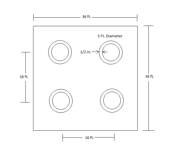
Prestressed concrete piles were originally proposed for the deep foundation design. Once design began it was determined that it would require multiple piles with large diameters in order to reduce the lateral deflection to an acceptable amount. Driving these large piles in such close proximity to the required depths was not feasible, therefore concrete drilled shafts with permanent steel casing were selected for the deep foundation design instead. For the deep foundation design at both the piers and abutments, four 5 feet diameter drilled shafts were selected. While the diameter is 5 feet in total, the drilled shafts have ½” thick steel permanent casing around the concrete. Making the diameter of the concrete 49 inches with a compressive strength of 6000 psi. The total length of the drilled shaft for the piers is 130 feet, with an embedment depth of 110 feet. For the abutments the total length of the drilled shafts are 110 feet embedded fully into the soil without any stick height. The following diagram displays the drilled shaft configuration for both the piers and abutments.

 Untitled


Bridge Shape

With the inputs finished into HEC-RAS, the minimum height of 12′ above high tide was kept.  The mean sea level is 0′, plus the high tide at 7′.  This puts the low chord of the bridge at 19′.  Even though the current model shows a pile design, the pile design is not complete.  Once a pile design is selected it can be inputted into HEC-RAS and the scour can be ran on the model.


Brige shape with old piles

Bridge Abutment

Scan0002

With an embankment height of 10 feet, the bridge abutment dimensions were determined as indicated on the drawing provided. Because the abutment is supported by piles, the bearing capacity was not determined for the soil directly beneath the abutment. The wall was checked for sliding and overturning. For sliding, the resistance force was calculated to be approximately 5,000 lb/ft with a driving force of 3,500 lb/ft. The abutment was resistant to sliding along the base. For overturning, the resistance moment was calculated to be 31,000 lb*ft/ft and the overturning moment was 13,500 lb*ft/ft. The abutment was safe from overturning.